73
EN
TABLE OF COUNTER DISPLAYED
Type
No. Description
Range
U/M Step
CO 0.0
total no. of boiler
operating hours
0 ..
99
h x 1000
0.1; from 0.0
to 9.9; 1; from
10 to 99
CO 0.1
total no. of burner
operating hours
0 ..
99
h x 1000
0.1; from 0.0
to 9.9; 1; from
10 to 99
CO 0.2
total no. of burner
ignitions
0 ..
99
h x 1000
0.1; from 0.0
to 9.9; 1; from
10 to 99
CO 0.3 total no. faults
0 ..
99
x 1 1
CO 0.4
total no. of
times installer
parameters
"tS"accessed
0 ..
99
x 1 1
CO 0.5
total no. of times
OEM parameters
accessed
0 ..
99
x 1 1
CO 0.6
time unitl next
maintenance
intervention
1 ..
199
months 1
TABLE OF ACTIVATED ALARMS/FAULTS
Type
No. Description
AL 00 Last activated alarm/fault
AL 01 Last but one activated alarm/fault
AL 02 Third from last activated alarm/fault
AL 03 Previous activated alarm/fault
AL 04 Previous activated alarm/fault
AL 05 Previous activated alarm/fault
AL 06 Previous activated alarm/fault
AL 07 Previous activated alarm/fault
AL 08 Previous activated alarm/fault
AL 09 Previous activated alarm/fault
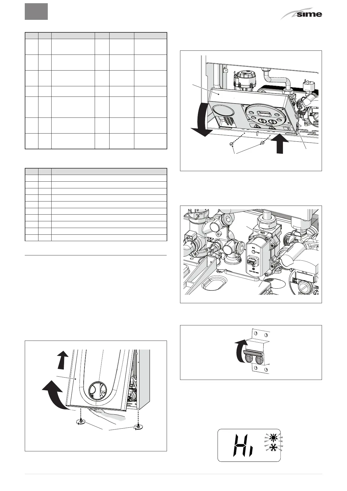
7.6 Checks and adjustments
7.6.1 Chimney sweeper function
The chimney sweeper function is used by the qualified
maintenance technician to check the gas pressure at the
nozzles, detect the combustion parameters and to measure the
combustion efficiency required by legislation in force.
This function lasts 15 minutes and is activated by proceeding
as follows:
– if the panel (2) has not already been removed, remove the
two screws (1), pull the front panel (2) forwards and release it
from the top by lifting it
1
2
Fig. 42
– remove the screws (3) securing the control panel (4)
– move the panel (4) upwards (a) but keeping it in the side
guides (5) to the end of travel
– bring it forwards and down (b) until it is horizontal
3
a
b
5
4
Fig. 43
– close the gas valve
– loosen the "nozzle pressure" point (6) and the screw of the
"supply pressure" point (7) and connect each one to a pressure
gauge
6
7
Fig. 44
– open the gas valve
– power the boiler by setting the main switch to "ON"
ON
Fig. 45
– press the button
s
until "SUMMER" mode
l
has been
selected
– press the buttons
o
and
>
at the same time for approximately
10 seconds until the message flashes on the display
alternating with the temperature of the delivery sensor and
the flashing symbols
o
and
>