TECHNICAL SPECIFICATION
20221529 / C 67
STEP signal
Circuits:.....................................................................4
Electrical: ...................................... 24V DC – 6 step/°
RATE OF TURN signal
Circuits......................................................................1
Electrical: ........................ +/-10V (+/-120°) (default),
+/-10V (+/-30°),
+/-10V (+/-300°),
+/-5V (+/-120°),
+/-5V (+/-300°),
+/-5V (+/-30°)
Note! Refer Rate of Turn scale dip switch settings, page 92, and to the
separate manual delivered for Rate of Turn Instrument.
Alarm output
Potential free .................................................. NO/NC
Running contact
Potential free .................................................. NO/NC
Refer Jumper settings on SCC board, page 93.
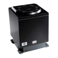
7.5 Physical Dimensions
GC80/GC85 Master Compass
Height: ................................................................. 438 mm (17.2”)
Width: .................................................................. 340 mm (13.4”)
Depth: ..................................................................340 mm (13.4”)
Weight: .................................................................... 23 kg (51lbs)
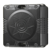
GC80 Expanded Control Unit
Height: ................................................................. 495 mm (19.5”)
Width: .................................................................. 364 mm (14.3”)
Depth: ....................................................................182 mm (7.2”)
Weight...................................................................... 14kg (31 lbs)