These echoes will be displayed at their correct bearing, but at a wrong range.
Second trace echoes can be recognized by their irregular shape. Since the period between
two subsequent transmitted pulses is subject to small variations, the second trace echo
appears undefined and hazy.
Second trace echoes are automatically suppressed by the radar when the interference
rejection is turned on. Refer "Rejecting radar interference" on page 55.
Sidelobe echoes
Radar antennas have a radiation pattern consisting of a main lobe and several very small
sidelobes. Most of the energy transmitted by the radar is radiated and received back on the
main lobe, and a very small part on the sidelobes. This has no effect in case of distant or small
targets, but the returns from a large target at short range (less than 3 NM) can generate, on
both sides of the main echo and at the same range, arcs or series of small echoes. These
effects, when they are an extension of the main echo, can cause momentary errors for the
tracking, and course and speed values given by the tracking can become unstable.
The problem can usually be eliminated or strongly reduced by an accurate adjustment of the
Sea control. Refer "Sea anti-clutter" on page 27.
Blind sectors
Funnels, masts or other obstructions (when located near the radar antenna) may cause blind
or shadow sectors, where the target visibility may be completely lost or strongly reduced.
Targets remaining in these sectors for a long time (more than 10 antenna revolutions) will be
considered lost, and the lost target alert will be triggered.
Low signal to noise ratio and signal to clutter ratio
In situations where the signal to noise or the signal to clutter ratio of the radar echoes is low
(small vessels in heavy sea or rain clutter, or big vessels close to the radar horizon), target
detection is poor and the tracking will not detect the target at each antenna revolution. This
will cause errors in the tracking, and it can range from missed information and up to
complete loss of the target when it is missed for 10 consecutive antenna revolutions.
Radar SART
A SART (Search And Rescue Transponder) is used for emergencies. These devices may be
either a radar-SART, or a GPS-based AIS-SART.
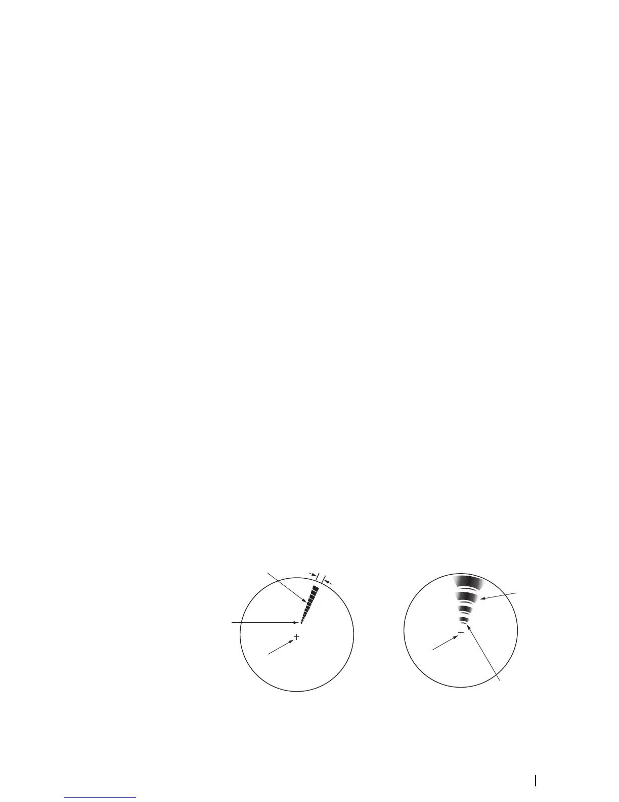
The radar-SART is used to locate a survival craft or distressed vessel by creating a series of
dots on the radar PPI. The range for detection of a radar-SART is normally about 8 NM, and its
signal may be triggered by any HD or X-Band radar.
Since the radar-SART is very near, side lobes from the radar antenna may show the responses
as a series of concentric arcs or rings. This effect can be removed by using the Sea anti-clutter
control. It is useful to observe the side lobes as they might be easier to detect in clutter
conditions, and they will confirm that the radar-SART is very close to own ship.