4 Select the type for the zone
Ú
Note: The line color is only applicable when the type is set to guard zone. The line color
is always white if the type is set to auto acquisition.
5 Save the changes by selecting the finish adjusting option in the menu
Ú
Note: If you exit the menu by pressing the exit key, the zone remains in edit mode. The
lines remain with dashed lines, and the zone is not active.
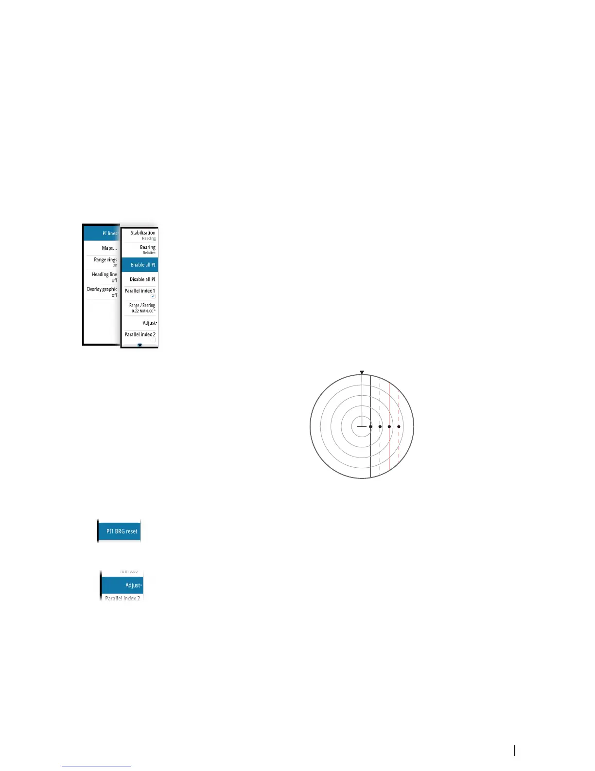
Parallel index lines
Parallel Index (PI) lines are used to visualize the distance to own vessel, other vessels or to
land objects. Two index lines can be used to indicate a corridor - typically used to visualize an
area you want to maneuver within.
The PI lines can be defined with north or heading stabilization, and with true or relative
bearing.
• North stabilization: the line direction is maintained with respect to north
• Heading stabilization: the line rotates with the vessel heading
• True bearings: the parallel index bearing is measured from the geographical north
• Relative bearings: the parallel index bearing is measured from the heading line
You can define four PI lines in the system, and they are identified with different color and
style:
• PI1: Grey solid line
• PI2: Grey dashed line
• PI3: Orange solid line
• PI4: Orange dashed line
You can turn each PI line on and off individually, and the position, bearing and truncating
can be set for each line.
Each PI line can be reset to be parallel to own ship's heading from the main menu.
Adjusting a PI line
Each PI line's range and bearing are shown in PI lines submenu.
You can adjust the line's settings from the selected line's Adjust menu option. The options
described in the next sections are available.
Adjusting range and bearing
1. Select the range or bearing menu options
-
The slider bar is displayed
2. Turn the rotary knob or use the up/down arrow keys to increase or decrease the slider bar
value
- The change is immediately committed and shown on the image
3. Press the exit key or the right arrow key to leave the edit mode
Ú
Note: Max range for a bearing line is 12 NM.
Navigation tools | R5000 Operator manual
45