Page 5-2 Robertson AP45 Autopilot
Installation
Simrad Robertson AS
Egersund - Norway
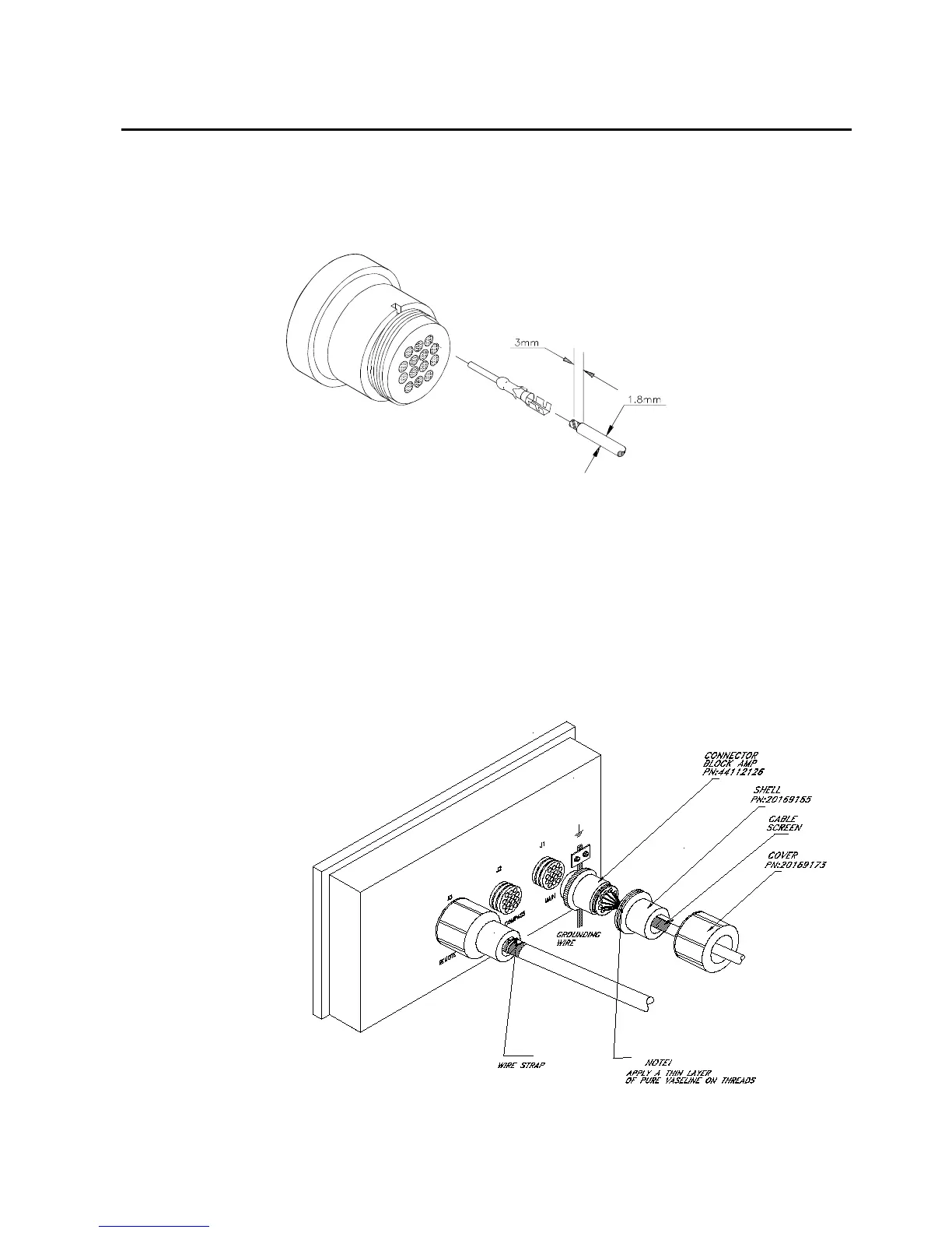
The cable conductors are connected to the connector block according to separate
connection diagrams. The following tools are required to crimp the connector pins
and sockets to the individual cable conductors.
Crimping tool :
Amp 90277-1
Extraction tool:
Amp 725840
Note!
Do not use other tools
than those specified!
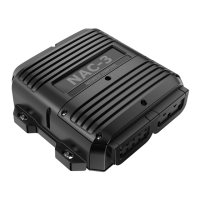
For protection against electro magnetic interference, all control unit connectors
must be fitted with the supplied metal shell and cover.
Strip about 1 cm (0.4") of the cable insulation and pull the screen backwards to
cover the insulation. Screw the connector block onto the actual control unit socket.
Screw the shell onto the connector block. Fix the cable screen to the shell by a wire
strap and tighten well to make sure the screen has good contact. Apply a thin
layer of pure Vaseline on the shell threads. Screw the cover onto the shell until it
makes good contact with the control unit cabinet.
The control unit has a ground terminal and must have a proper ground connection
to the hull. The grounding wire should be as short as possible and at least 10 mm
wide.
Fig. 5-3
Control unit - connector mounting
Connector assemble