Robertson AP45 Autopilot
Trouble shooting
Simrad Robertson AS
Egersund - Norway
Page 7-3
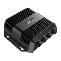
b. Enter the DEBUG-mode (see page 7-5) and verify that the sine and cosine
signals varies with the heading between approx. 0.5 and 4.5 volts. If not,
proceed to "c".
c. Check all connections between the fluxgate compass and the FI100 unit and
between the FI100 unit and the AP45 control unit. If found OK, proceed to "d".
d. Try a spare FI100 Fluxgate Interface PC-board.
G40A GYRO INTERFACE
a. Verify that the gyrocompass is working properly.
b. Refer to “G40A Gyro Interface Unit” page 5-9. and check that the G40A is
operating properly with special attention to LEDs as explained. If the unit is
not working properly, check all connections to the gyro compass and the AP45
control unit. If found OK, proceed to "c".
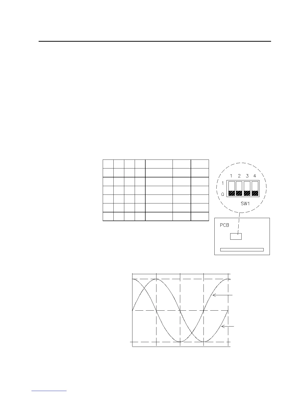
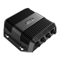
c. Check the signal transmission to AP45 by trying the different SW1 test
positions. Verify the sin/cos output levels and/or the AP45 display readings are
according to table.
1234 Angle SINCOS
I 0 0 I 0° 2,5V 2,5V
0 I 0 I 45° 4V 4V
I I 0 I 90° 4,5V 2,5V
0 0 I I 180° 2,5V 0,5V
I 0 I I 270° 0,5V 2,5V
000I45° STEP – –
d. Try a spare G40A Gyro Interface PC-board.
If the problem is still present after replacement of the
heading sensor or interface, the problem most
probably lies within the control unit.
90 180
270
0
360
0.5V
2.5V
4.5V
5V
SINE
COSI NE