A S3009 control unit
B S5100 Echosounder module
C Power cable
D Power control wire
S3009 power wiring
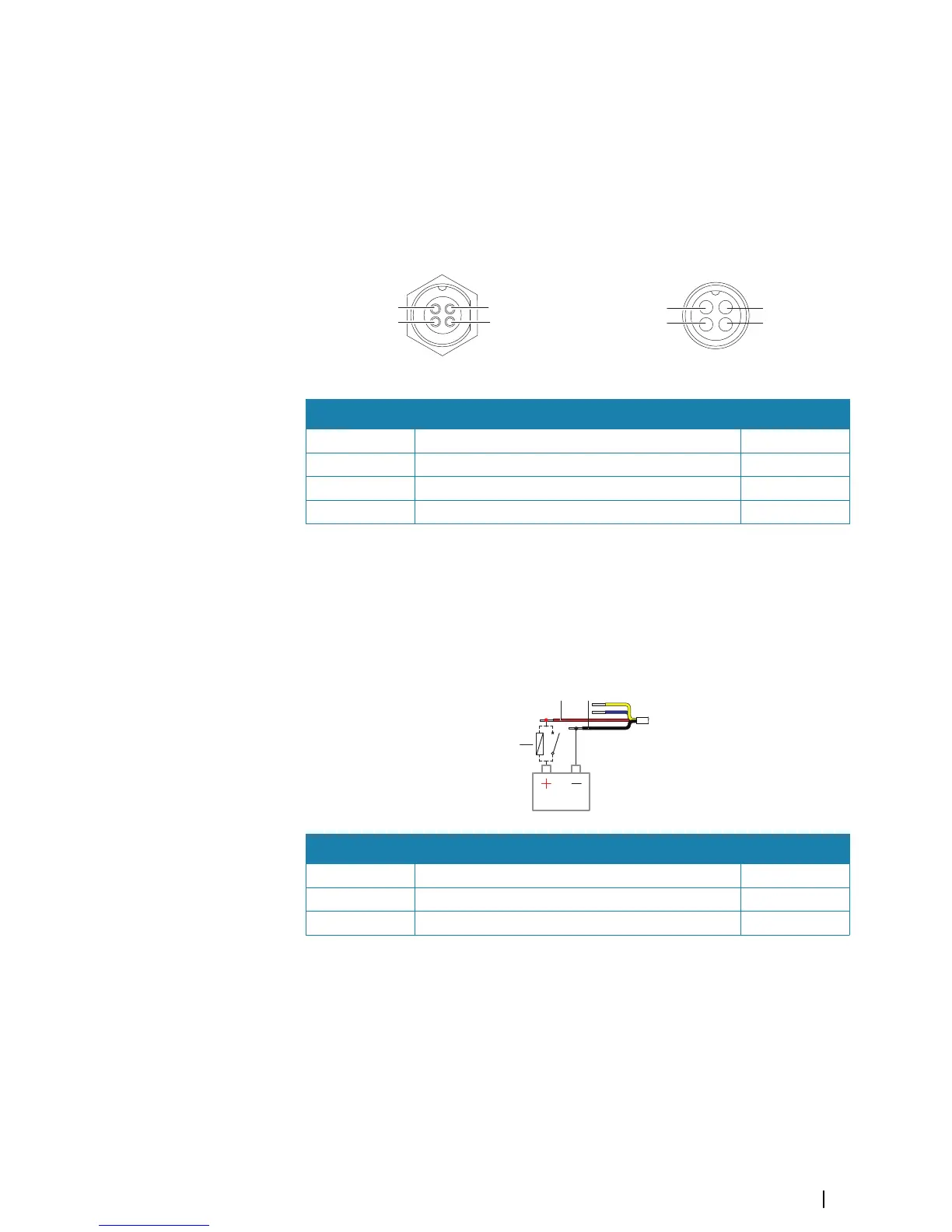
Power connector details
Cable plug (female)
Pin Purpose Color
1 DC negative Black
2 External alarm output (N/C isolated contact) Blue
3 External alarm output negative return Yellow
4 +12/24 V DC Red
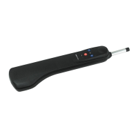
Power connection
The unit is designed to be powered by a 12 or 24 V DC system.
It is protected against reverse polarity, under voltage, and over voltage (for a limited
duration).
A fuse or circuit breaker should be fitted to the positive supply. For recommended fuse
rating, refer to the technical specification in the "Appendix" on page 47.
Key Purpose Color
A +12/24 V DC Red
B DC negative Black
C Fuse or circuit breaker
S5100 echosounder module power wiring
For S5100 echosounder module grounding and power connection, refer to separate wiring
instructions included with the module.
Ú
Note: For transducer connection refer to "Transducer wiring" on page 27. Separate
documentation included with the S5100 echosounder module shall not be used for
transducer wiring.
Wiring | S3009 Echo Sounder User Manual
33