0607SE Maintenance Manual 3-1 © Jan 2022
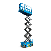
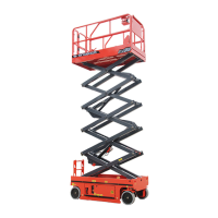
3 SYSTEM DESCRIPTIONS
POWER
The machine is powered by two 12V lead-acid batteries
in series connection or one 24V lithium battery which
drive a 24V DC motor on the power unit to boost the
geared pump to provide power to the system.
HYDRAULIC SYSTEM
The hydraulic system of the machine can be divided
into two parts: one part is used for controlling steer
function and the other part for controlling platform
lifting/lowering function.
When the electric motor operates, the hydraulic pump
directs pressurized oil to the function manifold which is
equipped with directional valves for controlling different
actions. To protect relevant components and avoid
pressure overload, the function manifold is provided
with relief valves.
ELECTRICAL SYSTEM
The electrical system uses two 12V lead-acid batteries
in series connection or one 24V lithium battery to drive
the reducer and travel motor and the motor on the
power unit, thus realizing drive, steer platform lifting/
lowering functions. The battery is charged from an
external power supply. The machine is equipped with a
breaker to protect the control system.
MACHINE CONTROL
SYSTEM
The functions of the machine are controlled with two
controllers in this system. A controller is located on the
right door of the machine and controls the platform up/
down functions. The other controller is located on the
platform and controls lift and drive functions. The
controller exchanges data through a high-speed data
bus.
SAFETY MEASURES
A series of sensors and limit switches are used to
provide signals for the controller.
• The level sensor measures the tilt angles in X and Y
axis of the machine, for details, please see B-11
Inspect Tilt Protection, page 5-16.
• The pothole guard limit switch serves to verify
whether the protective plates are properly deployed
in place. For details, please see B-12 Inspect
Pothole Guards, page 5-17.
• The up limit switch serves to resctrict the platform
lifting height. For details, please see C-3 Insepct
Lift Limit Switch, page 5-18.
• The down limit switch serves to control the platform
lowering in stages as well as the lowering speed.
For details, please see B-10 Test Drive Speed,
page 5-15 and C-4 Inspect Staged Lowering,
page 5-18.
• The weighing system (synergic operation of
pressure and angle sensors) serves to restrict the
platform loads. For details, please see C-2 Inspect
Platform Weighing System, page 5-18.