© Jan 2022 6-8 0607SE Maintenance Manual
REPAIR
BURN AND HIGH-PRESSURE
HAZARDS
Allow the hydraulic components to
cool to room temperature before
performing service. Loosen the
hydraulic hoses and fittings slowly to
relieve pressure.
NOTICE
When installing the removed hose and fitting, it must
be tightened according to the specified torque. See
Hydraulic Hose and Fitting Specifications, page
2-5.
1. Open the right door of the chassis and locate the
power unit.
2. Tag and disconnect the cables on the power unit.
3. Tag, disconnect and plug the hoses and fittings on
the hydraulic power unit.
4. Remove the screws installed at the bottom of the
power unit.
5. Remove the power unit.
Installation
Perform the procedure above in reverse order for
installation.
Removing the Lift Control Valve
Components
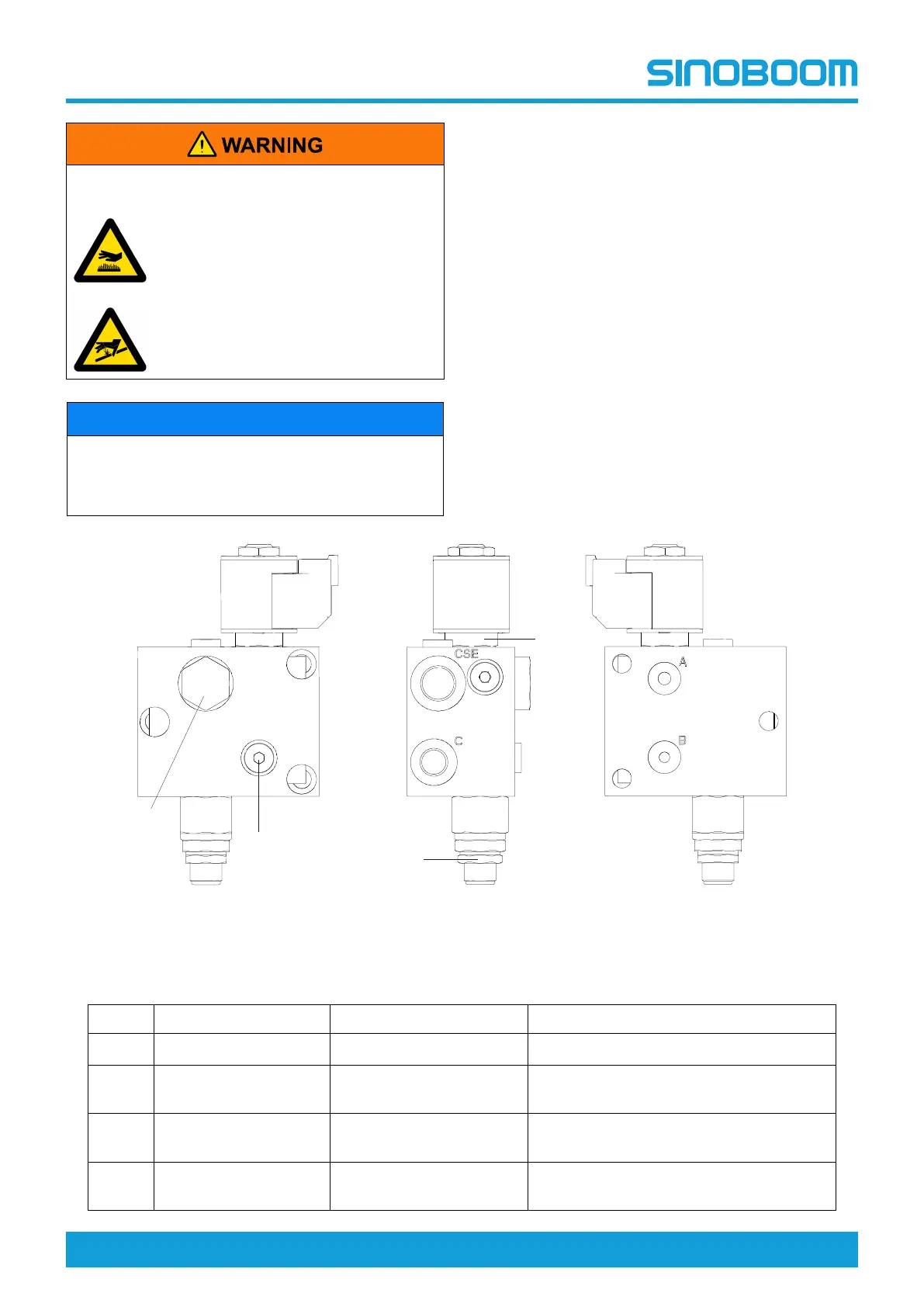
Figure 6-11 Upper lift control valve (PN.202040000171)
Table 6-2 Upper lift control valve (PN.202040000171)
NO. DESCRIPTION FUNCTION TORQUE
1 Check valve Prevents backflow of fluid 27.2Nm (20ft-lb)
2 Relief valve Safety valve to protect the
system
40~50Nm (29.5~37ft-lb)
3 Solenoid valve (with
filter screen)
To control the lowering
electrically
27.2Nm (20ft-lb)
4 Throttle screw (-
standard φ1.2)
\ 4Nm (3ft-lb)