REPAIR
0607SE Maintenance Manual 6-5 © Jan 2022
wheel bolts and install in sequence. Rear wheels:
align the mounting holes of the new wheel or the
one to be used with the center axis of bearing
housing, and then tighten the nut.
NOTICE
Wheel nuts should be torqued prior to first use of
machine and after each wheel removal. Check
torque every 3 months or 150 hours of operation.
Removing the Reducer & Drive Motor
The reducer & drive motor not only serves a power
drive but also helps in securing the front wheels,
therefore, before removing the reducer & drive motor,
support the machine on a suitable structure or place a
jack of ample capcity under the chassis.
NOTICE
Be sure to disconnect the battery charger and main
power from the machine before removing the reducer
& drive motor.
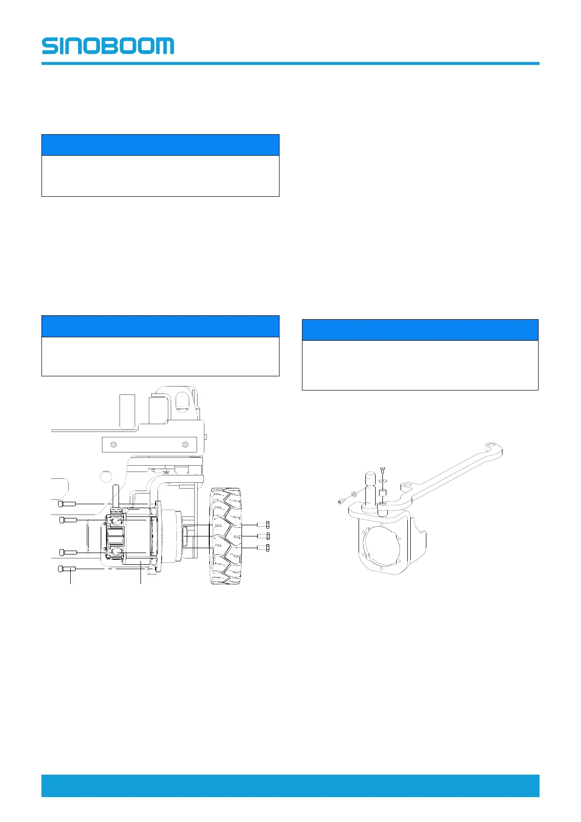
Figure 6-7
Removal of reducer and drive motor
1. Place the machine on a solid, level surface.
2. Place a jack of sufficient capacity under the side of
chassis to be removed. Lift the jack to make the
wheel off the ground.
3. Remove the wheel assembly, refer to Tires and
Rims, page 6-3.
4. Tag and disconnect the electric wiring to the
reducer & drive motor.
5. Use a suitable lifting device to support the reducer
& drive reducer.
6. Remove the bolt #1 securing the reducer & drive
motor to the wheel support, and remove the reducer
& drive motor #2.
Installation of reducer and drive motor
1. Align the mounting holes of reducer & drive motor
with those of the wheel support.
2. Apply threadlocker Loctite 272 to the bolts,and intall
in turns.
3. Tighten the bolts with a torque wrench.
4. Connect the electric wiring.
5. Install the wheel assembly. Refer to Tires and
Rims, page 6-3.
Removing the Front Wheel Bracket
NOTICE
When installing the removed hose and fitting, it must
be tightened according to the specified torque. See
Hydraulic Hose and Fitting Specifications, page
2-5.
Be sure to use a lifting device with adequate capacity to
lift the chassis. Be sure to place the lifting device at a
proper location on the chassis.
Figure 6-8
1. Disconnect the electrical components and wiring on
the drive motor.
2. Remove the bolt, washer and bearing #2 connected
to the steer linkage of the front wheel.
3. Remove the retaining bolt and washer #1 of the
front wheel bracket.
4. Remove the front wheel bracket.