19
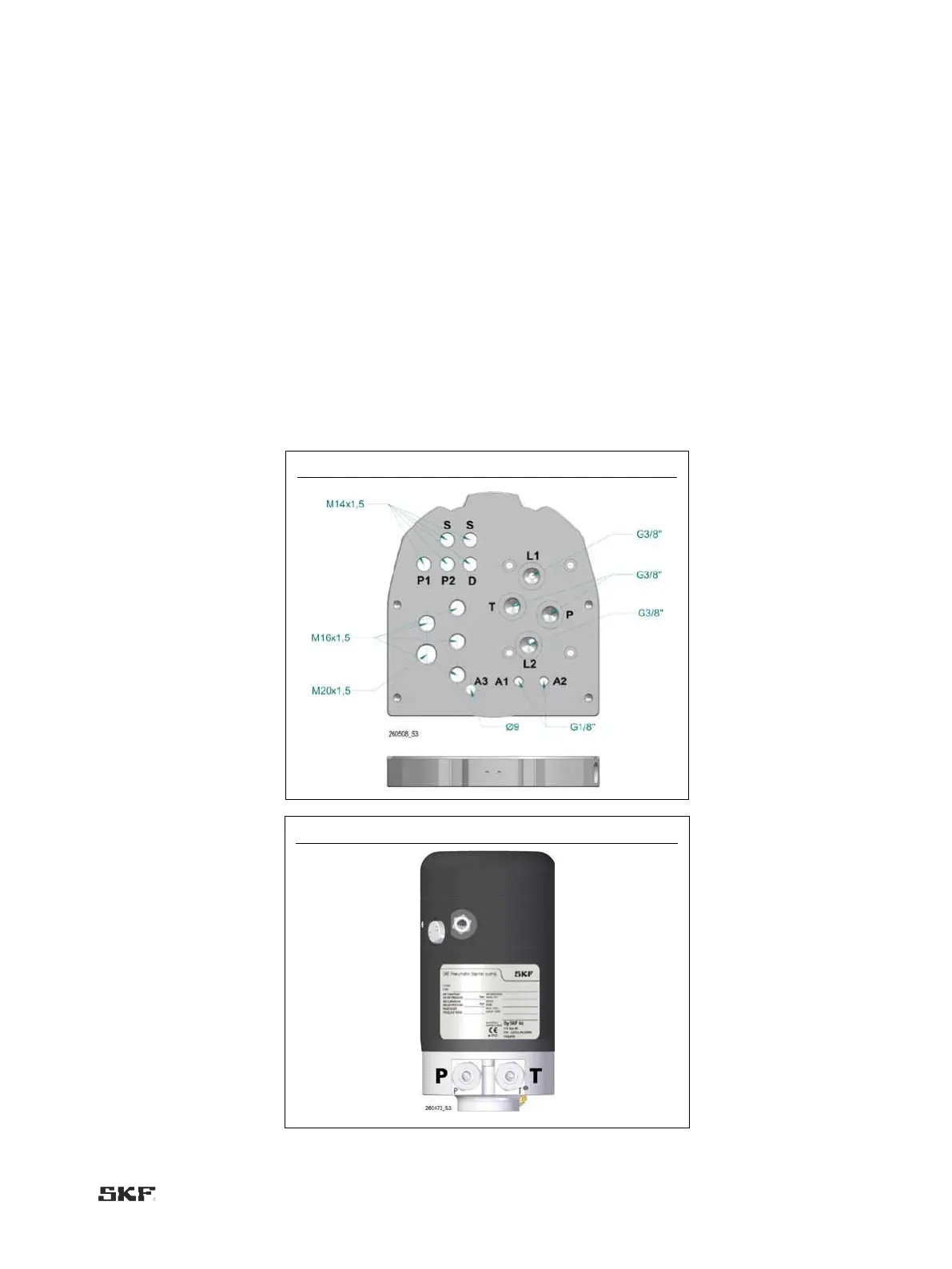
4.2.1 Connections
Lubricant connections:
" lubricant outlets (1 or 2 pcs; line 1 out, line 2 out), G3/8”, hose Ø 12 mm or Ø 1/2” (L1, L2)
" pressure inlet from the pump (G3/8), DIN 2353 shear ring coupling for a Ø 12 mm pipe (P)
" tank outlet for the pump (G3/8), DIN 2353 shear ring coupling for a Ø 12 mm pipe (T)
Compressed air connections:
" compressed air supply from the pressure air regulator to the changeover valve unit, (G1/8) pin plug ø8 mm (A1)
" compressed air supply for the pump, (G1/8) pin plug ø8 mm (A2)
" exhaust air outlet (A3)
Electrical connections:
" pumping centre 2 or shut-off valve (2 pcs), connector M12 (S) (M14x1)
" low level switch, female connector M12 (D) (M14x1)
" pressure control (2 pcs), connector M12 (P1/channel 1, P2/channel 2) (M14x1)
" power supply, cable bushing M20 x 1.5 1 pcs
" accessories (e.g. external alarm, interlocking), M16 x 1,5 cable sleeve, 4 pcs, cable ø4–10 mm
Fig. 4 Maxilube connections

 Loading...