EasyManuals Logo

SKF MAX-1-2-230-IF105-R-V2 Assembly Instructions

SKF MAX-1-2-230-IF105-R-V2
51 pages
To Next Page IconTo Next Page
To Previous Page IconTo Previous Page
Page #26 background imageLoading...
Page #26 background image
26
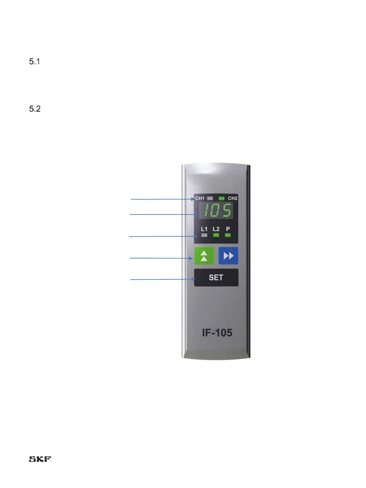
5. IF-105 user interface
General description
IF-105 is the user interface for the internal control unit of the SKF Maxilube changeover valve unit.
Lubrication programming, alarm resetting and lubrication event monitoring can be performed with the user
interface.
Main components
Figure 9 illustrates the structure of the IF-105 user interface. It includes a display (1), LEDs for pressurisation
(2), browsing buttons (3), a setting/function button (SET; 4) and LEDs for the lubrication channels (5).
5
1
2
3
4
Figure 10. IF-103 user interface

Table of Contents

Other manuals for SKF MAX-1-2-230-IF105-R-V2

Questions and Answers:

Question and Answer IconNeed help?

Do you have a question about the SKF MAX-1-2-230-IF105-R-V2 and is the answer not in the manual?

SKF MAX-1-2-230-IF105-R-V2 Specifications

General IconGeneral
BrandSKF
ModelMAX-1-2-230-IF105-R-V2
CategoryWater Pump
LanguageEnglish

Related product manuals