20
4.2.2 Commissioning with Maxilube ECOlid set and MPB pump
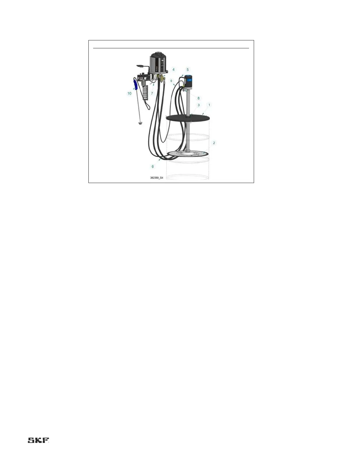
Fig. 6 Maxilube, ECO lid set and MPB pump
1. Ensure that the surroundings of the pumping centre are clean. Impurities in the system will prevent trouble-free
operation and cause damage at the lubrication point.
2. Reserve a container for excess grease.
3. Check the condition of the lubricant barrel. Any damage on the surface of the barrel will prevent the follower plate
from being lowered (Fig. 6, pos. 2).
4. Remove the barrel’s original lid and press the follower plate (Fig. 6, pos. 2) tightly against the lubricant in the
barrel. Make sure that air is removed from below the follower plate and that the central hole of the follower plate
starts to fill with lubricant.
5. Place the lid (Fig. 6, pos. 1) on top of the lubricant barrel. Fasten the lid onto the lubricant barrel with wing
screws.
6. Pass the pump through the lid onto the middle hole of the follower plate. Make sure that the pump is firmly
attached to the follower plate.
7. Connect the grease filter (Fig. 6, pos. 4) to the bottom plate connection P (Fig. 4).
8. Connect the compressed air hose (Fig. 6, pos. 5) to the pressure air regulator’s pin plug and the pump’s
compressed air connection.
9. Connect a 3/8 grease hose (Fig. 6, pos. 6) to the pump’s connection P (Fig. 5). Make sure that the other end of
the hose is in the container reserved for excess grease.
10. Start the pump by opening the pressure air regulator’s valve. When the hose has filled up, stop the pump by
closing the pressure air regulator’s valve and detach the hose from the pump’s connection P.
11. Connect the filled hose to the pump’s connection T (Fig. 5) and Maxilube’s connection T (Fig. 4).
12. Connect another 3/8 grease hose (Fig. 6, pos. 6) to the pump’s connection P and the grease filter (Fig. 6, pos. 4).
13. Detach the compressed air hose from the pressure air regulator and connect it to Maxilube’s connection A2 (Fig.
4).
14. Connect a ø8 mm plastic hose between the pressure air regulator and Maxilube’s connection A1 (Fig. 4).
15. Attach the low level switch (Fig. 6, pos. 8) to the pump and the low level switch cable (Fig. 6, pos. 9) to the
switch.
16. Connect the low level switch cable (Fig. 6, pos. 9) to Maxilube’s bottom plate connection D (Fig. 4) and the
cables of the channel pressure control units and shut-off valves to the pumping centre as described in the wiring
diagram.
17. Set the pressure of the pumping centre to 4 bar (60 psi) with the pressure air regulator’s pressure control device
(Fig. 2, pos.III).

 Loading...