23
Replacing the lubricant barrel
Pressurised lubricant
Ensure that the system will not start during barrel replacement. Shut off the compressed air
supply by lifting up the shut
-off valve button (Fig. 8, pos. e) or set the compressed air pressure
to 0 bar with the pressure regulator and the pressure gauge (Fig.
8). Any residual pressure in
the system when opening or disconnecting components may cause components to be thrown or
lubricant to spray, causing
injury to people or damage to the environment.
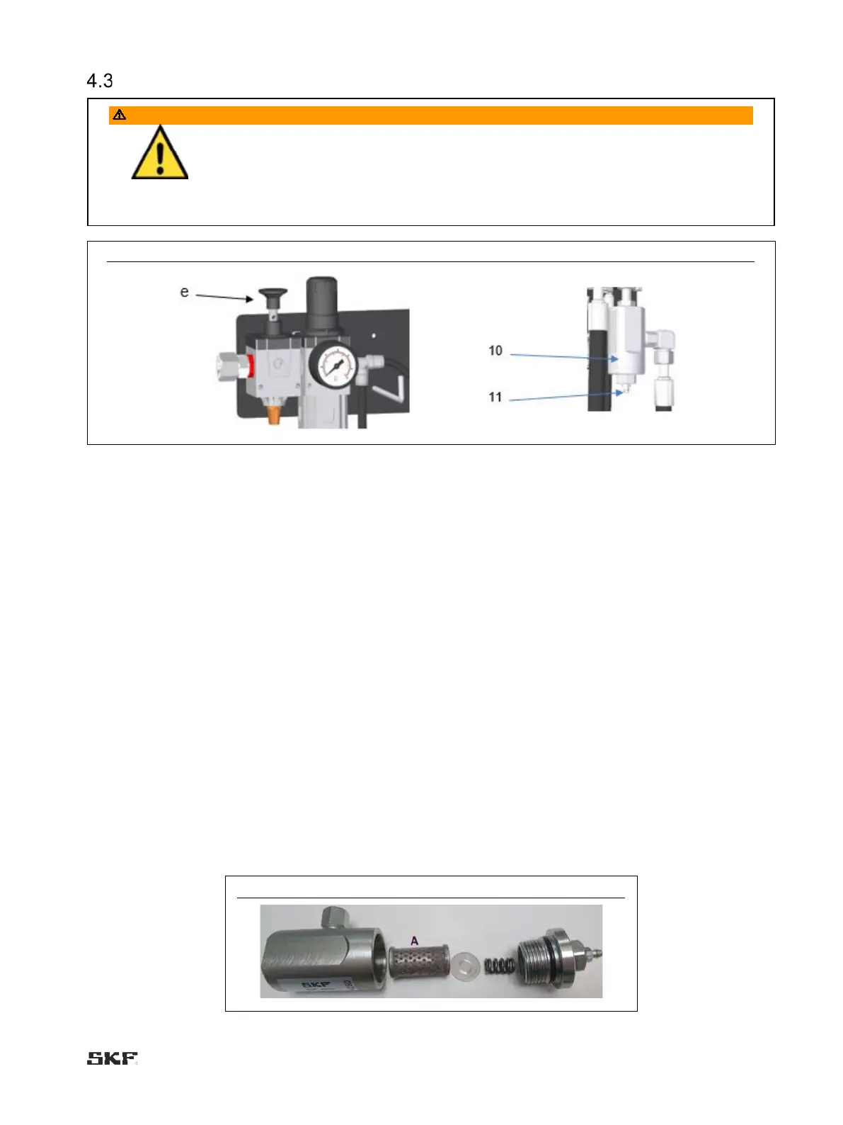
Fig. 8 Shut-off valve button (e), grease filter (10) and bleed screw (11)
4.3.1 Maxilube ECO with lid set and MPB pump
1. Ensure that the surroundings of the pumping centre are clean. Impurities in the system will prevent trouble-free
operation and cause damage at the lubrication point.
2. Switch off the power at the pumping centre when replacing the barrel.
3. Lift the pump out of the lubricant barrel and place it on the pump bracket or on a clean base. Be careful not to
damage the suction inlet at the bottom of the pump.
4. Remove the lid (Fig. 6, pos. 1) from the top of the barrel.
5. Remove the follower plate (Fig. 6, pos. 2) from the bottom of the barrel with an air gun (Fig. 6, pos. 10). Loosen the
follower plate by feeding compressed air under the follower plate through the middle hole.
6. Use the handles to lift the follower plate out of the barrel.
7. Replace the lubricant barrel.
8. Press the follower plate tightly against the lubricant in the barrel. Make sure that air is removed from below the
follower plate and that the central hole of the follower plate starts fills with lubricant.
9. Place the lid on top of the lubricant barrel. Fasten the lid onto the lubricant barrel with wing screws.
10. Pass the pump through the lid onto the middle hole of the follower plate. Make sure that the pump is firmly attached
to the follower plate.
11. Depressurise the grease filter (Fig. 8, pos. 10) by opening the bleed screw (Fig. 8, pos. 11) in the filter plug.
12. Clean the grease filter and the filter cartridge (Fig. 9, pos. A), or replace the filter cartridge if necessary.
13. Switch on the pumping centre. Reset any low level alarm by pressing the “Alarm acknowledgement” button in the
control unit.
14. Make a pumping centre operation test run by pressing the “Extra lubrication” button on the control unit.
Fig. 9

 Loading...