HGM9510 GENSET PARALLEL UNIT
HGM9510 Genset Parallel Unit ISSUE 2013-08-06 Version 1.1 Page 25 of 65
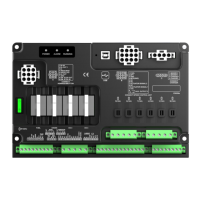
7 WIRING CONNECTION
HGM9510 controller’s rear as following:
Description of terminal connection:
Connected with negative of starter battery.
Connected with positive of starter battery. If wire
length is over 30m, better to double wires in parallel.
Max. 20A fuse is recommended.
Connected with B+ via emergency stop button.
B+ is supplied by 3 points, rated 16A
B+ is supplied by 3 points, rated 16A
Connected
to starter coil
B+ is supplied by 2 points, rated 7A
B+ is supplied by 2 points, rated 7A
B+ is supplied by 2 points, rated 7A
Connected with charger’s D+ (WL) terminals. Be
hanging in the air If there is no this terminal.
Ground connected is active (B-)
Ground connected is active (B-)
Ground connected is active (B-)
Ground connected is active (B-)
Ground connected is active (B-)
Ground connected is active (B-)
 Loading...