HGMS61 Genset Controller User Manual Page 17 of 47
6 CONNECTIONS
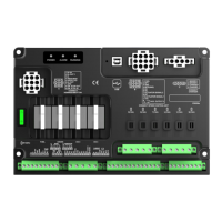
6.1 HGMS61M CONTROLLER PANEL
Fig.2 – HGMS61M Controller Panel Drawing
Table 9– HGMS61M Terminal Connection Description
Relay normally open, rated 16A, volt-free contact
output.
Relay normally open, rated 16A, volt-free contact
output.
B+ is supplied by 21 points, rated 7A.
Ground connection is active (B-).
Ground connection is active (B-).
Ground connection is active (B-).
Ground connection is active (B-).
Connect to temperature sensor.
Oil Pressure Sensor
Input
Connect to pressure sensor.
Controller inside has been connected to B-.
Charging Generator D+
Input
Connect to D+ (WL) terminal. If without, the terminal
is not connected.
Speed Sensor Input
Or ECU CAN Input
HGMS61MCAN: connect to ECU CANBUS,
impedance-120Ω shielding wire is recommended, its
single-end connect with ground.
HGMS61M: connect to speed sensor, shielding wire