- 29 -
No.EX##-OMY0004
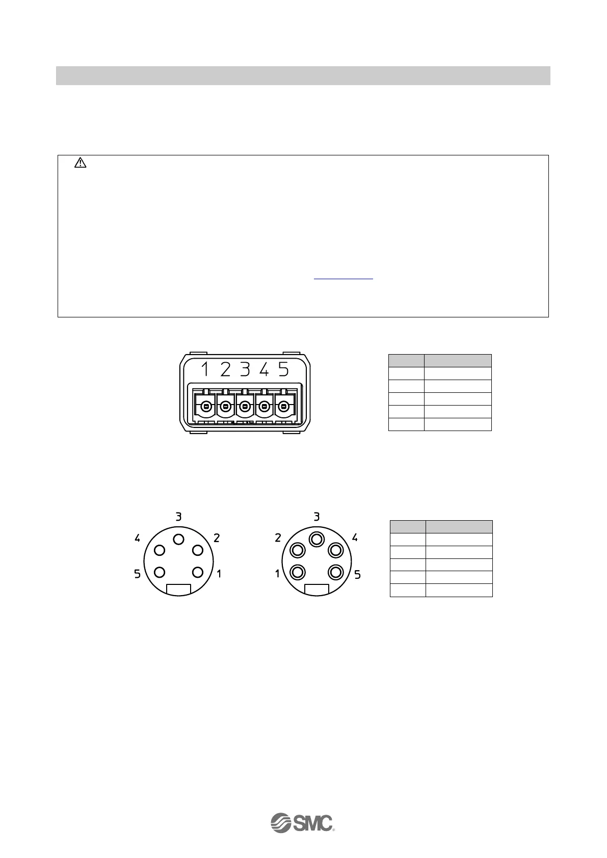
7.2.1. Bus/Power connection
The EX245-FPS1/2/3 has two Power connectors (XD1/2) and two PROFINET communication connectors
(XF1/2). If only one connector is used, cover the unused connector with a blanking cap so that the
protection rating of IP65 is maintained.
Caution
"Blanking caps must be fitted to all unused bus & power connector ports to ensure an IP65 rating and to
prevent eye exposure to the light beam from the SCRJ connectors."
This rating must be maintained to guarantee PROFIsafe functionality.
For reasons of EMC a secure connection to the cable shield must be established on the PROFINET
(XF1/2) and Power (XD1/2).
Power and bus lines must be installed correctly.
To prevent manifold components of the EX245 from being damaged the supply lines for the electronics
and for the load voltage must be protected externally with a fuse.
All external supplies must meet the requirements of Section 2.2.2 of this manual.
Maximum loop through current between connectors must not be exceeded. Refer to EX245-FPS1/2/3
specifications table for details
The SI unit makes use of a CLASS 1 LASER product. Do not stare into beam visible at XF1 and XF2

 Loading...


