- 32 -
No.EX##-OMY0004
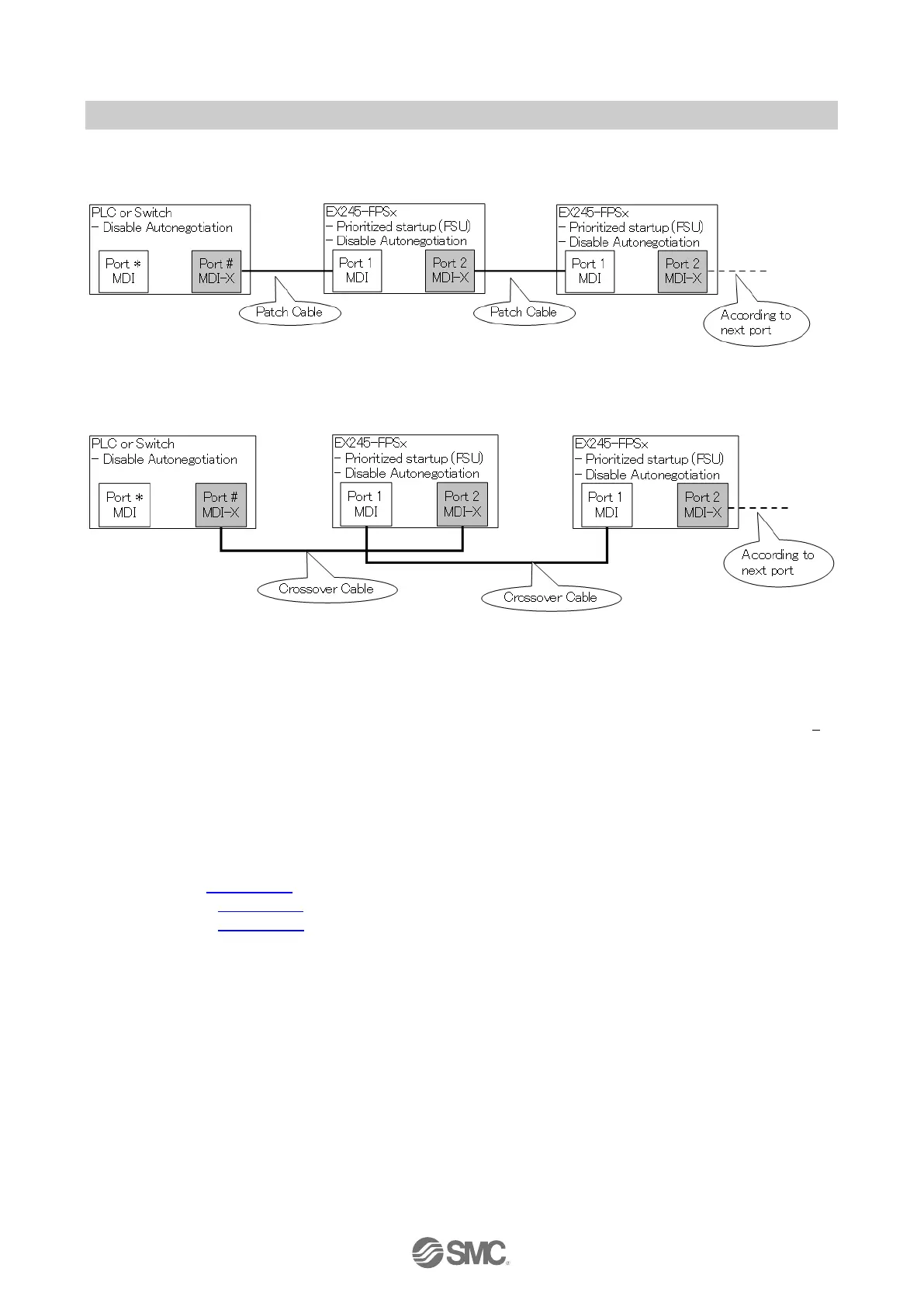
Connection example
Case 1
Case 2
Fig. 7-13 Connection examples when “Disable autonegotiation” is selected
7.2.2. FE terminal
The SI Unit must be connected to FE (Functional Earth) to divert electromagnetic interference. Connect
the grounding cable using the FE terminal screw on the SI Unit. The other end of the grounding cable
should be terminated to ground potential. For maximum protection the grounding cable should be as thick
and short as reasonably possible.
7.2.3. Sensor/Load/Power connection
Regarding the wiring of each module, refer to following section:
Safe input: Section 10.3
EX245-DX1: Section 11.3
EX245-DY1: Section 12.3
 Loading...


