EasyManuals Logo
Home>SMC Networks>Control Unit>EX245-FPS1

SMC Networks EX245-FPS1 User Manual

SMC Networks EX245-FPS1
113 pages
To Next Page IconTo Next Page
To Previous Page IconTo Previous Page
Page #32 background imageLoading...
Page #32 background image
- 31 -
No.EX##-OMY0004
Note
If a copper communications cable is used and the “Disable autonegotation” option is selected,
you must select the correct network cable, refer to Fig 7-11, 7-12, 7-13.
Auto crossover function is not available when the ‘Disable autonegotiationoption is selected.
Auto crossover function shall be capable of switching over their twisted pair ports automatically
between MDI and MDI-X pin assignment.
Port Connection
Usable Cable
Port 1 (XF1) to Port 2 (XF2)
Patch cable
Port 1 (XF1) to Port 1 (XF1)
Crossover cable
Port 2 (XF2) to Port 2 (XF2)
Crossover cable
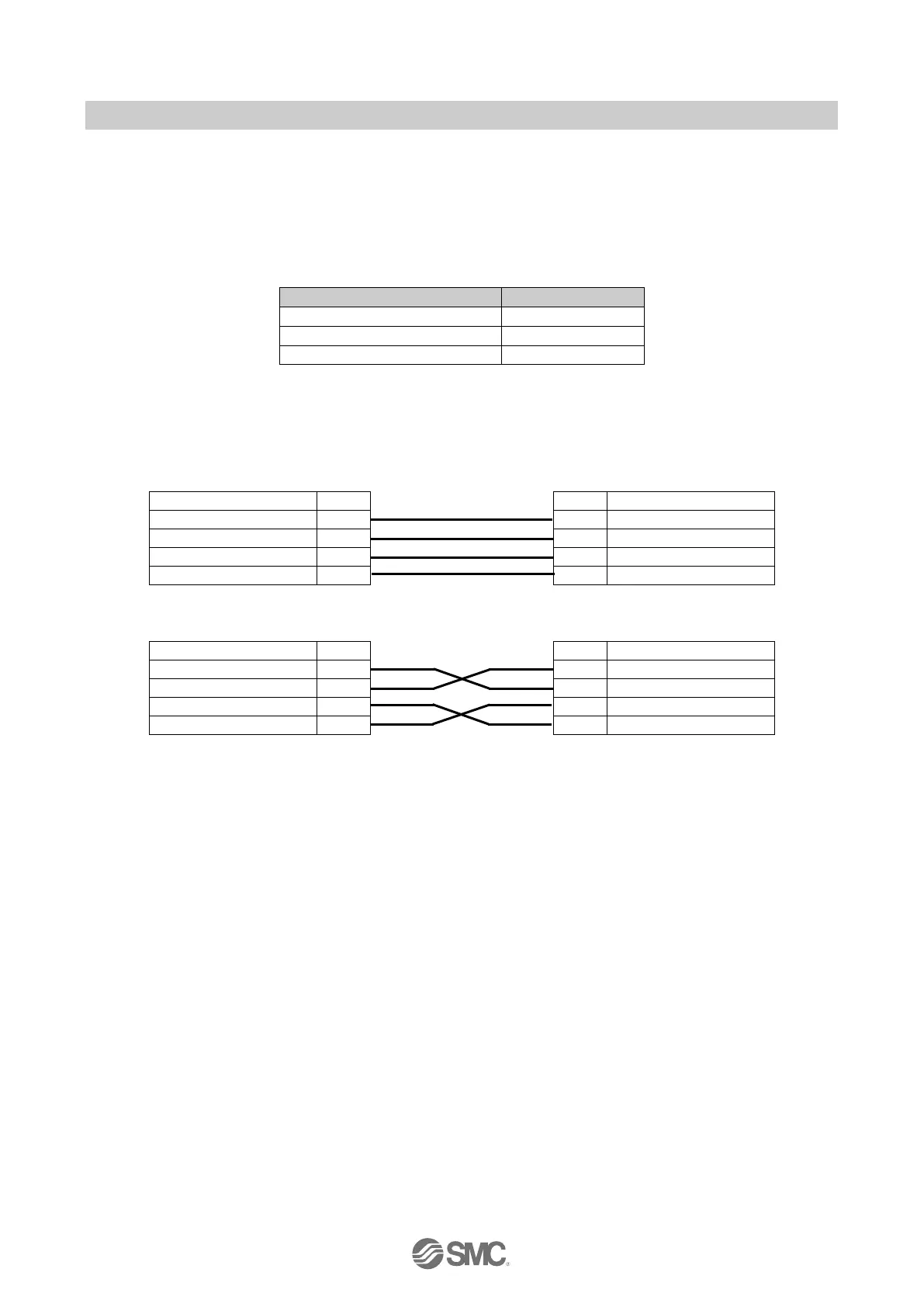
Fig. 7-11 Usable cable types when “Disable autonegotiationis selected
The following figure Fig.7-12 shows two different cable wiring.
Patch cable
M12 MDI
Pin
Pin
M12 MDI-X
TD+ Transmit data+
1
1
RD+ Receive data+
RD+ Receive data+
2
2
TD+ Transmit data+
TD- Transmit data-
3
3
RD- Receive data-
RD- Receive data-
4
4
TD- Transmit data-
Crossover cable
M12 MDI
Pin
Pin
M12 MDI
TD+ Transmit data+
1
1
TD+ Transmit data+
RD+ Receive data+
2
2
RD+ Receive data+
TD- Transmit data-
3
3
TD- Transmit data-
RD- Receive data-
4
4
RD- Receive data-
Fig. 7-12 Patch and Crossover Cable details

Table of Contents

Questions and Answers:

Question and Answer IconNeed help?

Do you have a question about the SMC Networks EX245-FPS1 and is the answer not in the manual?

SMC Networks EX245-FPS1 Specifications

General IconGeneral
BrandSMC Networks
ModelEX245-FPS1
CategoryControl Unit
LanguageEnglish

Related product manuals