- 35 -
No.EX##-OMY0004
8.1.4. Configuration steps
Enter the modules in your configuration program corresponding to the actual module layout and a
"Diagnostics type" module if required. If the configuration does not match the actual layout, the connection
to the IO Controller will not be established and the EX245-FPS1/2/3 error LEDs will flash.
Configuration steps:
Enter one of the “Diagnostics type” modules in Slot 5 if required.
Enter one of the “Output Status Unit” module in Slot 5 when without any of “Diagnostics type”, or in Slot 6
if Slot 5 has one of “Diagnostic type” module.
Enter all other modules that are connected on the left hand side of the SI Unit (max. 8 modules).
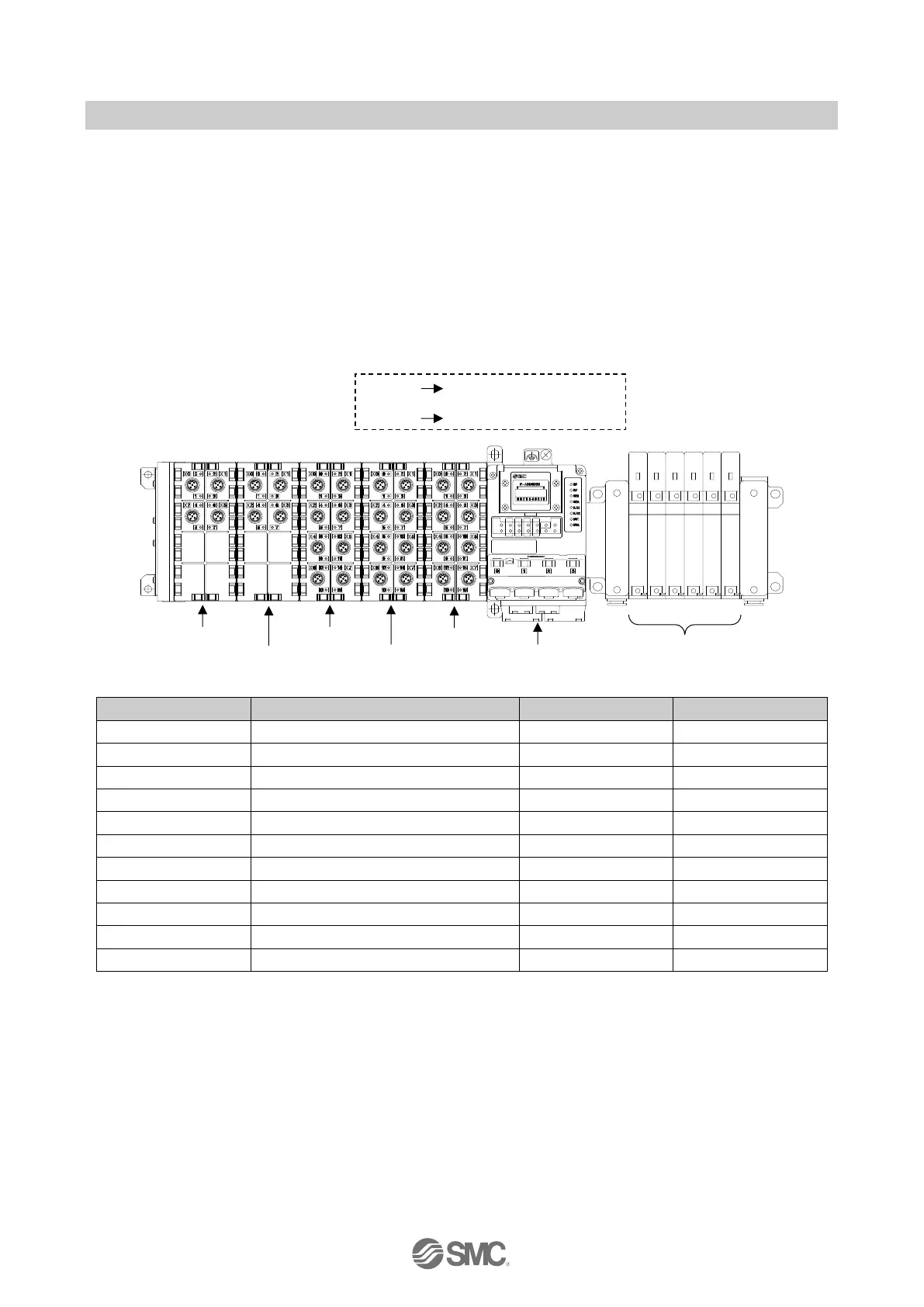
Example of a configuration which uses Module Passivation (Safety Mode (Module Passivation/xxx))
Diagnostics type 2 (Logical Modules)
Output Status Unit (Logical Modules)
EX245-DX1 (Physical Modules)
EX245-DX1 (Physical Modules)
EX245-DX1 (Physical Modules)
EX245-DY1 (Physical Modules)
EX245-DY1 (Physical Modules)
Fig. 8-1 Example of assignment of modules
NOTE
In this example slot 1 is occupied by either of these modules: Safety Mode (Module Passivation/Words) or Safety
Mode (Module Passivation/Bits)
When you change the module configuration in your configuration program, you need to turn off the supply for the
logic/sensors "US1" and turn it on again.
When you use Logical Module (Output Status Unit), it must be added before any of the Physical Modules i.e. it must
occupy a lower slot address than any Physical Modules. Do not add the logical module after any Physical Modules

 Loading...


