EasyManuals Logo

SMC Networks PFCA7 Series User Manual

SMC Networks PFCA7 Series
83 pages
To Next Page IconTo Next Page
To Previous Page IconTo Previous Page
Page #19 background imageLoading...
Page #19 background image
-19-
No.PF※※-OMA1002
Wiring Method
Connections
Connections should only be made with the power supply turned off.
Use a separate route for the product wiring and any power or high voltage wiring. If wires and cables are
routed together with power or high voltage cables, malfunction may result due to noise.
If a commercially available switching power supply is used, be sure to ground the frame ground (FG)
terminal. If a commercially available switch-mode power supply is connected for use, switching noise will be
superimposed and it will not be able to meet the product specifications.
In that case, insert a noise filter such as a line noise filter/ferrite between the switching power supplies or
change the switching power supply to a series power supply.
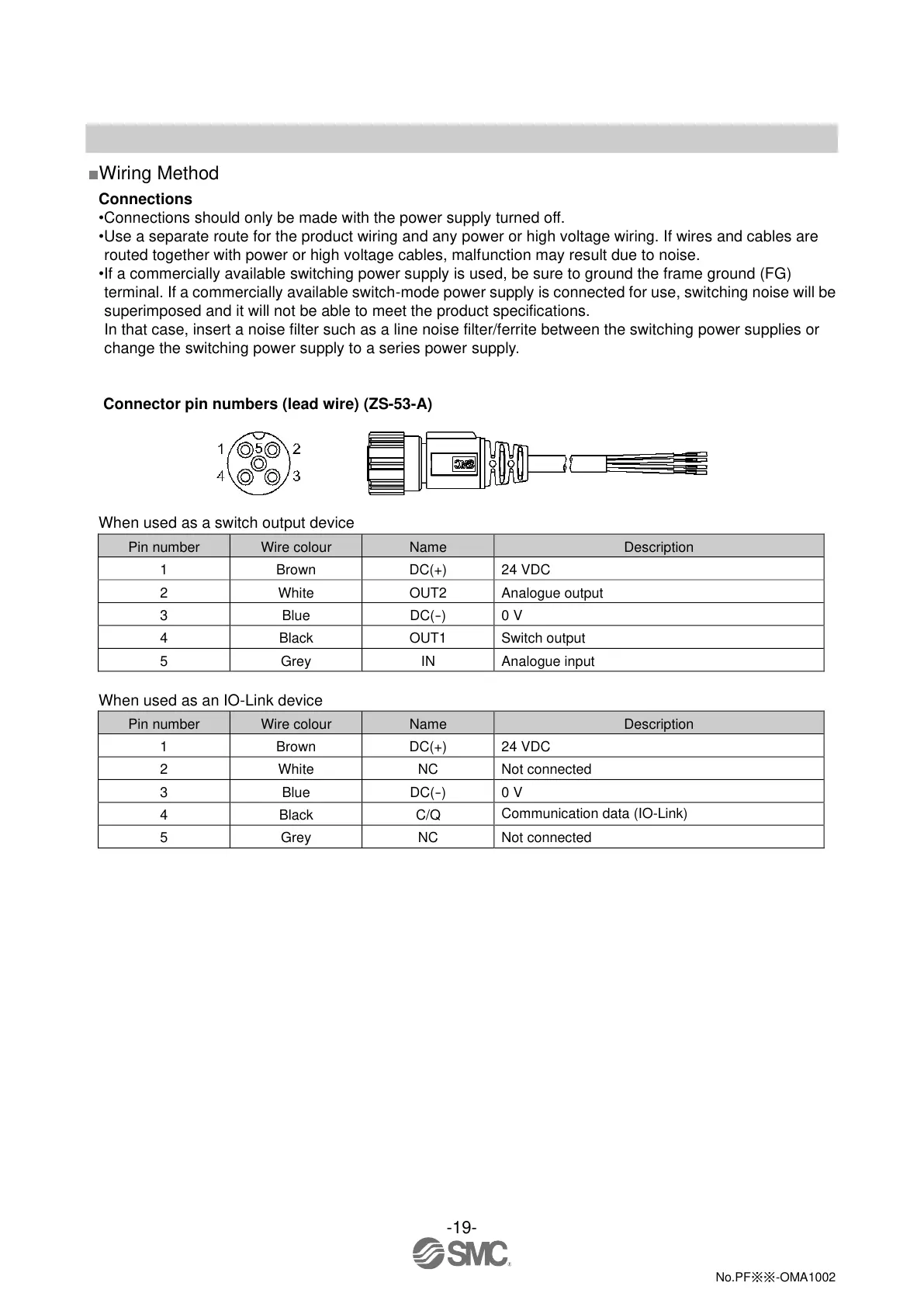
Connector pin numbers (lead wire) (ZS-53-A)
When used as a switch output device
Pin number
Wire colour
Name
Description
1
Brown
DC(+)
24 VDC
2
White
OUT2
Analogue output
3
Blue
DC(
-
)
0 V
4
Black
OUT1
Switch output
5
Grey
IN
Analogue input
When used as an IO-Link device
Pin number
Wire colour
Name
Description
1
Brown
DC(+)
24 VDC
2
White
NC
Not connected
3
Blue
DC(
-
)
0 V
4
Black
C/Q
Communication data (IO-Link)
5
Grey
NC
Not connected
2023-12-20 14:49
DL145266

Questions and Answers:

Question and Answer IconNeed help?

Do you have a question about the SMC Networks PFCA7 Series and is the answer not in the manual?

SMC Networks PFCA7 Series Specifications

General IconGeneral
BrandSMC Networks
ModelPFCA7 Series
CategoryController
LanguageEnglish

Related product manuals