EasyManuals Logo

SMC Networks PFCA7 Series User Manual

SMC Networks PFCA7 Series
83 pages
To Next Page IconTo Next Page
To Previous Page IconTo Previous Page
Page #13 background imageLoading...
Page #13 background image
-13-
No.PF※※-OMA1002
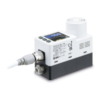
Names and Functions of Product Parts
Body
Connector pin numbers
(on the product)
1
DC(+)
2
OUT2 (Analogue output)
3
DC(
-
)
4
OUT1 (C/Q)
5
IN (Analogue input)
Description
Function
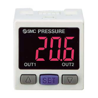
Display
Refer to the figure below.
Piping port
For piping connections. IN represents "inlet" and OUT represents "outlet".
Connector
Lead wire with M12 connection.
UP button
DOWN button
Use this button to select the mode and the display shown on the Sub display, or increase
or decrease the numerical value.
The assignment of the UP and DOWN buttons changes depending on the display rotation
angle.
For details, refer to "Display rotation angle setting" on page 39.
SET button
Press this button to change the mode and to set a value.
2023-12-20 14:49
DL145266

Questions and Answers:

Question and Answer IconNeed help?

Do you have a question about the SMC Networks PFCA7 Series and is the answer not in the manual?

SMC Networks PFCA7 Series Specifications

General IconGeneral
BrandSMC Networks
ModelPFCA7 Series
CategoryController
LanguageEnglish

Related product manuals