-14-
No.PF※※-OMA1002
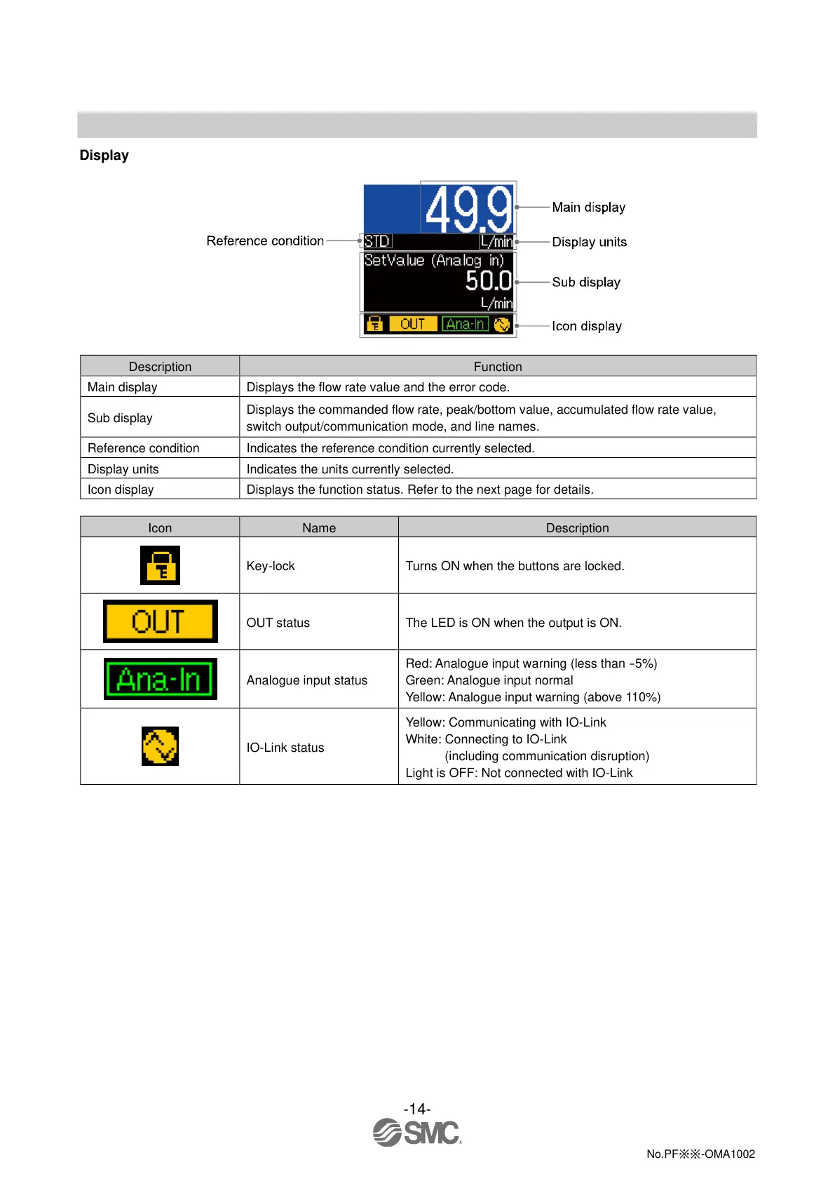
Display
Displays the flow rate value and the error code.
Displays the commanded flow rate, peak/bottom value, accumulated flow rate value,
switch output/communication mode, and line names.
Indicates the reference condition currently selected.
Indicates the units currently selected.
Displays the function status. Refer to the next page for details.
Turns ON when the buttons are locked.
The LED is ON when the output is ON.
Red: Analogue input warning (less than
-
5%)
Green: Analogue input normal
Yellow: Analogue input warning (above 110%)
Yellow: Communicating with IO-Link
White: Connecting to IO-Link
(including communication disruption)
Light is OFF: Not connected with IO-Link
2023-12-20 14:49
DL145266
 Loading...


