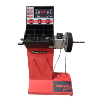
Snap‐onEEWB330AHandspinWheelBalancer
AfterthemeasuringruntheOP.3readingappears.
Mountthetireandinflatecorrectly(seenotebelow).
Note:Formountinganddemounting(tirechanger)and
tireturningorreadadjustmentontherim,alwaysapply
asufficientamountoftirelubricantonthetirebeads
andtherimedgesandshoulders.Eachtimetheposition
ofthetireischangedontherim,inflate thetiretoover
pressure(approx.3.0bar/43psi)thendeflatetocorrect
tirepressure.Makesurethecenteringlineispositioned
onthetirebead.
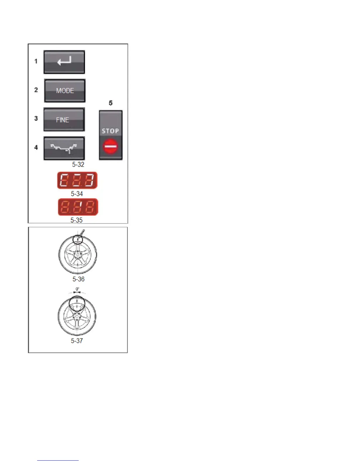
Clampthewheel.Positionthevalveexactlyperpendicular
toandabovethemainshaft.PresstheENTERkey(1)to
acquirethevalveposition.OP.4appears(Fig.5‐34).Spin
thewheel(START).Themeasuringruniscarriedout.After
themeasuringruntworeadingsarepossible:OP.5‐H1
Furtheroptimizationisnotrecommended,but
possible.OP.5–I(1ReferencemarkFig.5‐35).Continue
withtheOPprogram.ReadingOP.5‐H1IfOP.5‐H1
appears,furtheroptimizationisnotrecommended,since
themeasurementvalueswhichactivatedthe
optimizationrecommendationarebelowthelimitvalue.
However,itispossibletocontinueoptimizationforthe
mostsilentpossiblewheelrunning,reducingimbalances
belowthelimitvalue(criticalvehicle).
Tocontinueoptimization.TocontinuewiththeOP
programproceedasspecifiedforOP.5–I(givenbelow).To
abortoptimization‐PresstheSTOPkeytoreturntothe
balancingprogramandbalancethewheelaccordingto
thereadings(5.9).
ReadingOP.5–I(1ReferencemarkFig.5‐35).Afterthe
measuringrunreadjustthewheelfollowingthe
directionindicatorandmakeachalkmarkontheright
sideofthetireexactlyperpendiculartoandabovethe
mainshaft.Readjustthetireontherimsothatthe
referencemarkmadeisalignedwiththevalve(usetire
changer).Clampthewheelonthebalancerandreadjust
ituntilthevalveisexactlyperpendiculartoandabove
themainshaft.PresstheENTERkey(1)toacquirethe
valveposition.TheOP.6readingappears (Fig.5‐
34).
Spin wheel (START)