6
Introduction Data and Power Connections
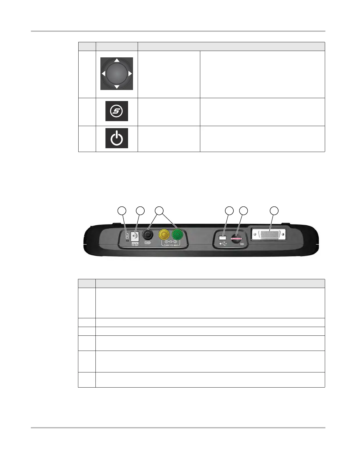
1.2 Data and Power Connections
Connectors and jacks for the scope multimeter, data communication cables and the AC/DC power
supply are located on the top of the diagnostic tool.
Figure 1-2 Top view
3
Directional - Thumb
pad rocker type buttons
Buttons move the cursor or highlight in their
respective direction:
• Up (b)
• Down (d)
• Left (e)
• Right (c)
4
S (Shortcut) - Push type
button
Programmable function button that can provide a
shortcut for performing a variety of routine tasks.
Refer to Configure Shortcut Button‚ on page 117 for
additional information.
5
Power (On/Off) - Push
type button
Turns the diagnostic tool on and off. Also, press and
hold for 5 seconds for emergency shutdown.
Item Button Description
Item Description
1
Battery Status Indicator LED
• Green - battery is fully charged
• Red - battery is charging
• Amber - indicates there is a battery issue (correct before operating)
2 DC Power Supply Jack - AC/DC power supply connection
3 Scope/Multimeter Jacks - Scope and multimeter lead connections
4
Mini USB Jack - USB cable connection used to connect the diagnostic tool to a personal
computer
5
Micro secure digital (uSD) Card - contains operating system programming. IMPORTANT The
uSD card must be installed for the diagnostic tool to operate. Do not remove the uSD card
while the diagnostic tool is powered on.
6
Data Cable Connector - Data cable connection used to connect the diagnostic tool to a vehicle
data link connector