63
Scope Multimeter Operation and Controls
5.5 Operation and Controls
This section describes the general operation and controls used to configure the scope or meter to
perform testing. All three functions share similar control panel settings, see Control Panel and
Settings‚ on page 65 for additional information.
i The information in the following sections is intended as a guide and general overview of the
controls and functions used within the Scope Multimeter. Not all the settings or controls described
throughout this section are applicable with all functions.
z To open a scope multimeter function:
1. Select the Scope Multimeter icon from the home screen.
2. Select either Lab Scope, Graphing Multimeter or Digital Multimeter from the menu.
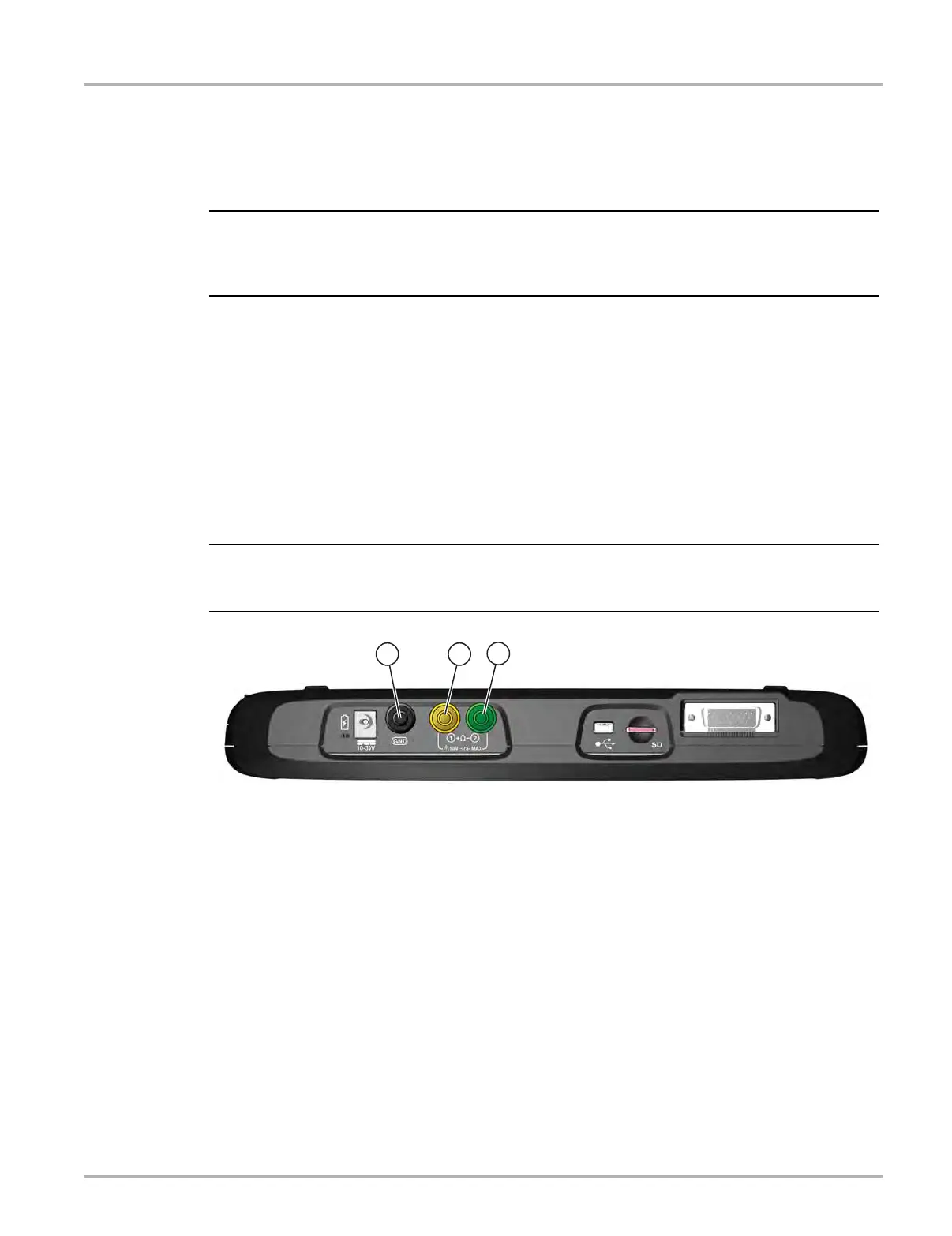
5.5.1 Test Lead / Probe Connection
Standard “safety type” test lead jacks are located on the top of the diagnostic tool, and are
compatible with many test leads and probes. Insert the applicable test lead or probe terminal end
into the jack to compete the connection.
To avoid damaging test leads, do not pull on the wire when removing the leads from their jacks.
Pull only on the lead terminal end.
1— Ground Jack (Black)
2— Channel 1 Jack (Yellow)
3— Channel 2 Jack (Green)
Figure 5-9 Scope Multimeter Test Lead Jacks