105
Guided Component Tests Screen Layout and Icons
6.2 Screen Layout and Icons
This section describes the Guided Component Tests control icon functions and screen layout.
6.2.1 Screen Layout
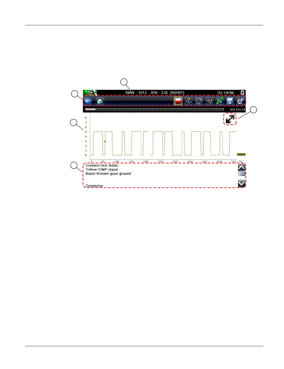
1— Vehicle Identification
2— Toolbar—contains control icons
3— Main Body—displays menus, information, meter scales and signal traces
4— Information Panel—displays test information
5— Expand/Collapse icon—toggles Main body view between full and split views
Figure 6-2 Test screen
Main Body
The main body of a Guided Component Test screen may display any of the following:
• Selectable Menu - Select menu options using the touch screen or control buttons.
• Component Information - Provides information to assist you with testing.
• Test Meter - The test meter can display up to two signals, simultaneously. Signal and display
adjustments are made through the Control Panel. Signals are displayed using a grid with
scales, both vertical (y axis), and horizontal (x axis).
Meter touch screen functionality is limited, however you can adjust the zero baseline position
(0 value) of the signal on the horizontal scale by touching and dragging the zero baseline
marker.
2
3
4
5
1