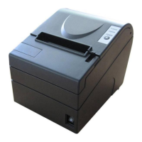
BTP-2002NP User’s Manual
- 15 -
User may check the current setting status of the interface by printing a configuration table. The
default setting is as follows:
Baud rate: 9600bps
Data bit: 8
Parity bit: None
Stop bit: 1
Handshaking: Hardware
Serial interface connection example:
Host Printer
FG-----------------FG
TXD---------------RXD
RXD--------------TXD
CTS---------------RTS
DSR--------------DTR
DTR--------------DSR
SG ----------------SG
6.3 RS-485 Serial Interface
Signal definition and functions for DB25 connector are shown as below:
Pin
No.
Signal
Name
Signal
Direction
Functions
1 FG - Frame Ground
2
3
SD1
SD2
Output Send data
4
5
RD1
RD2
Input Receive data
7 SG
- Signal Ground
8
9
DR1
DR2
Output
When selecting DTR/DSR, the signal is used to indicate the printer status.
1) DR1>DR2 means that the printer is ready to receive data;
DR1<DR2 means that the printer is busy.
2) When selecting XON/XOFF, this signal indicates if the printer is connected
and ready to receive data properly. SPACE means the printer is ready to
receive data. If the signal is always DR1>DR2, it means the printer is ready
to receive data. Except the cases as below, the signal is always DR1>DR2:
·From power-on to printer ready for data reception;
·When the printer is tested itself.
10
11
CS1
CS2
Input
The signal indicates if the host can receive data. CS1>CS2 means that the
host can receive data; CS1<CS2 means that the host can’t receive data.
When selecting DTR/DSR, the printer shall transmit data after confirming it.
(Except the data transmitted via DLE EOT and GS a)
When selecting XON/XOFF, the printer doesn’t check this signal.