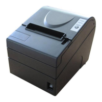
BTP-2002NP User’s Manual
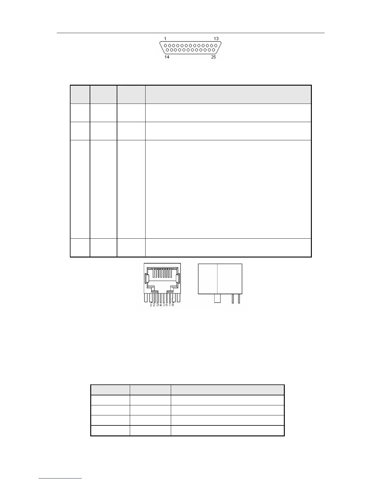
The 25 PIN D-SUB connector
Signal definition and functions for RJ45 connector are shown as below:
Pin
No.
Signal
Name
Signal
Direction
Functions
1
2
SD2
SD1
Output Sending data
3
6
RD2
RD1
Input Receiving data
5
4
DR1
DR2
Output
When selecting DTR/DSR, the signal is used to indicate if the printer is
busy or not.
1) DR1>DR2 means the printer is ready to receive data; DR1<DR2
means the printer is busy.
2) When selecting XON/XOFF, this signal indicates whether or not the
printer is connected and ready to receive data correctly. SPACE
means the printer is ready to receive data. When this signal is
always DR1>DR2, it means the printer is ready to receive data.
Except the cases as below, the signal is always DR1>DR2:
·From power-on to printer ready for data reception;
·When the printer is in self-test.
7
8
GND -
Signal Ground
Interface connector (RJ45 10P8C)
6.4 USB interface
1) Specifications:
Data transmission: Universal Serial Bus Specification Revision 1.1
Connector (printer side): USB “B” type connector(standard)
2) Interface signal definition and signal functions:
Pin No. Signal Name Function
1 VBUS +5V
2 DATA- Printer data transmit line minus
3 DATA+ Printer data transmit line plus
4 GND Ground
- 16 -