20
MODULYS GP Green Power 2.0 range from 400 to 600 kVA - Ref.: IOMMODGPXX07-EN 00
3. ELECTRICAL INSTALLATION
3.1-2
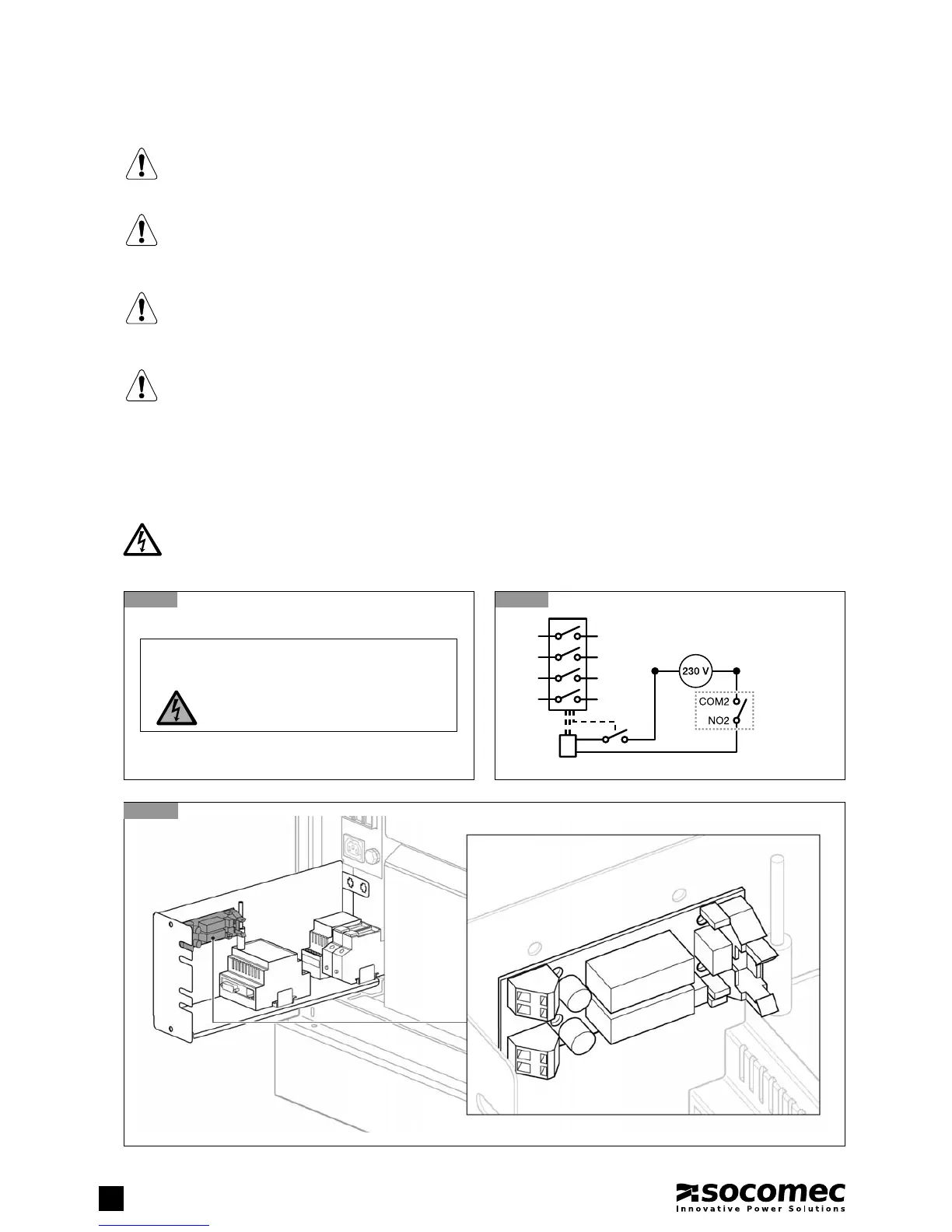
Backfeed electrical diagram
3.1-1
Warning label (supplied with the equipment)
BACKFEED PROTECTION
The UPS is set up for the installation of external protection devices against the backfeed of dangerous voltages on the auxiliary
backup mains power supply line (AUX MAINS SUPPLY). The current rating of the switching device has to follow the instruction
outlined in chapter ‘Electrical Requirements’.
DANGER! RISK OF ELECTRIC SHOCK!
The installer must attach the warning label in order to warn electrical technicians about dangerous backfeed situ-
ations (not caused by the UPS).
Before working on this circuit
- Isolate the Uninterruptible Power System (UPS)
- Then check for Hazardous Voltage between all terminals
including the protective earth
Risk of Voltage Backfeed
B
L1
L2
L3
N
UPS output voltage
Backfeed Card
Dry Contact
3.1-3
Backfeed card
The UPS is designed for transient overvoltages in category II installations. If the UPS is part of the building’s elec-
trical circuit, or is likely to be subject to transient overvoltages in category III installations, additional external
protection must be provided, either on the UPS or in the AC power supply network powering the UPS.
WARNING!
As specified in 62040-3 Appendix 3: Non-linear Load Reference, in the event of three-phase non-linear loads
connected downstream of the UPS, the neutral current on the load can be 1.5 - 2 times higher than the phase
current. This must be considered when estimating the correct size of the output and the auxiliary neutral cables.
WARNING!
Protective earthing conductor (PE) must have sufficient current-carrying capacity. The PE cable core size must be
chosen according to the PROTECTIVE CURRENT RATING of the earth circuit which depends on the provision and
location of protective overcurrent devices.
NOTE!
3-Phase 4-Wire Input Power is required. The unit can be installed in TN, TT and IT AC distribution systems (IEC 60364-3).