40
MODULYS GP Green Power 2.0 range from 400 to 600 kVA - Ref.: IOMMODGPXX07-EN 00
5. CONNECTIONS
5.3-1
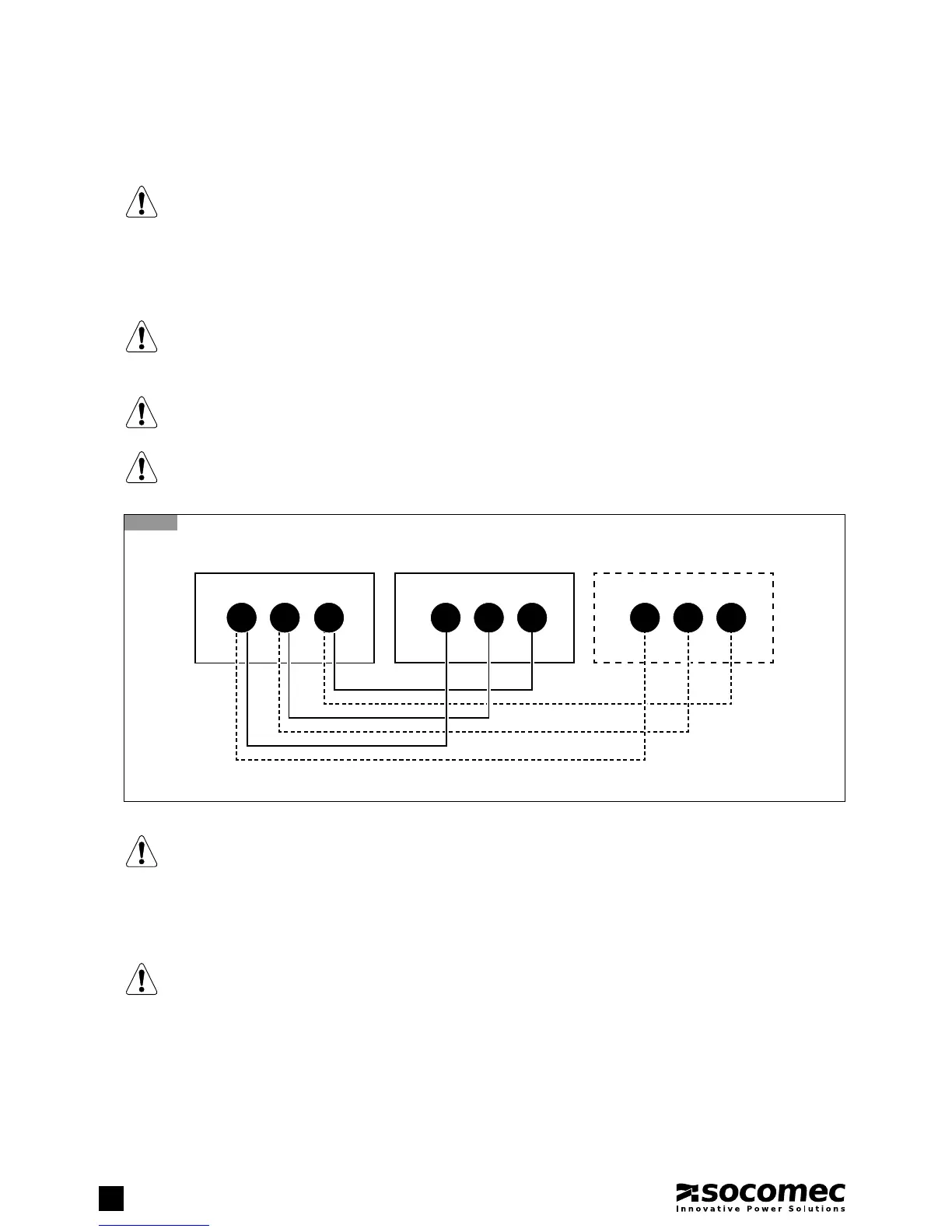
5.3. EXTERNAL BATTERY CONNECTION
NOTE!
For further information refer to the battery cabinet manual.
• Remove the plastic terminal block protection.
• Connect the protective earth (PE) cable.
• Connect the cables between the coupling cabinet terminals (X200) and battery cabinet terminals.
WARNING!
Strictly observe:
- the polarity of each individual string (refer to the figure below);
- the cable cross section (refer to ‘Electrical requirements’ chapter).
WARNING!
Cabling errors with inversion of battery polarity may cause permanent damage to the equipment.
Reassemble the plastic terminal block protection.
NOTE!
When battery cabinets not supplied by Socomec are used, the installer is responsible for:
- checking electrical compatibility;
- checking the presence of appropriate protective devices (fuses and switches that ensure the cables are protected
from the UPS to the battery cabinet).
Once the UPS is switched on – before closing the battery switches – check the battery parameters on the control
panel menu. For further information, refer to ‘Menu’ chapter.
NOTE!
Not all battery/capacity combinations are available.
+ N -
BATTERY CABINETBATTERY CABINETCOUPLING CABINET
+ N -
+ N -