41
MODULYS GP Green Power 2.0 range from 400 to 600 kVA - Ref.: IOMMODGPXX07-EN 00
ENGLISH
5.4. OTHER CONNECTIONS
NOTE!
Before carrying out any operations on the unit read the Safety standards chapter carefully.
WARNING! RISK OF TIPPING OVER!
Before carrying out any operations, ensure the UPS is secured at the feet.
WARNING! RISK OF TIPPING OVER!
The modules must be inserted from the bottom upwards and removed from the top downwards to ensure the unit
remains stable.
WARNING!
Before removing any module, ensure that the remaining power modules can support the load.
WARNING!
It is only possible to remove the bypass module when the UPS is in normal mode or in maintenance bypass mode
(refer to ‘operating modes’ chapter). Before removing the bypass ensure that the units are not in bypass mode.
5. CONNECTIONS
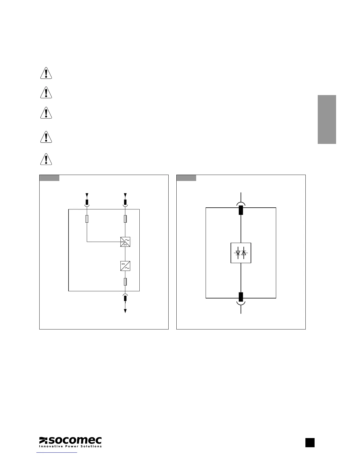
5.4-1
Power module electrical diagram
X2
F1/F2
80 A
F3/F4/F5
80 A
F6/F7/F8
80 A
400 Vac 3ph+N 50 Hz
INPUT MAINS
+/-400 Vdc 3 W
INPUT BATTERY
400 Vac 3ph+N 50 Hz
UPS OUTPUT
X1 X1
5.4-2
Bypass module electrical diagram
AUXILIARY MAINS
400 Vac 3ph 50 Hz
400 Vac 3ph 50 Hz
UPS OUTPUT
X3X4