19
ENGLISHENGLISH
MODULYS GP Green Power 2.0 range from 400 to 600 kVA - Ref.: IOMMODGPXX07-EN 00
3-1
3. ELECTRICAL INSTALLATION
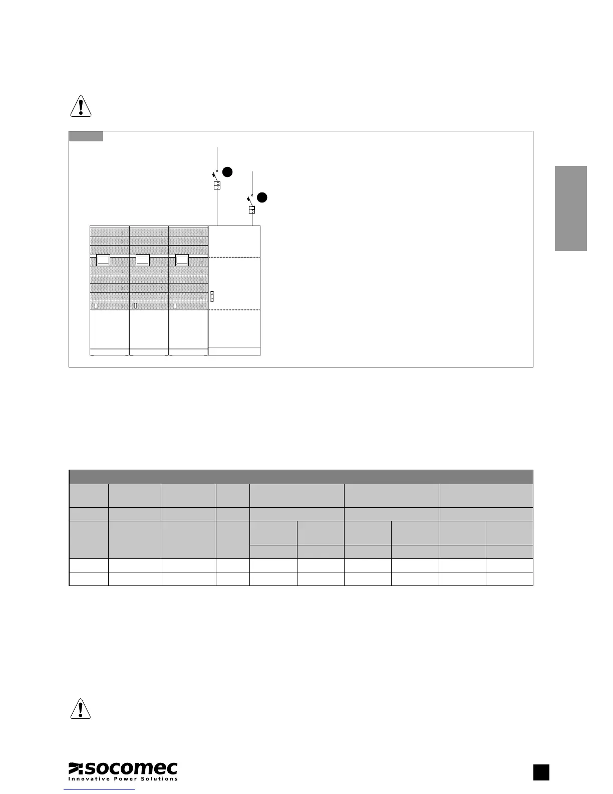
A
B
Key
A Input mains magneto-thermal switch
B Auxiliary mains magneto-thermal switch
3.1. ELECTRICAL REQUIREMENTS
The installation and system must comply with national plant regulations.
The electrical distribution panel must have a sectioning and protection system installed for input and auxiliary mains.
RCD is not necessary when the UPS is installed in a TN-S system.
RCD is not allowed on TN-C systems.
If a RCD is required a B-type should be used.
Size of input protection devices
Model
rating
Breaker
Input
(1)
Breaker
Aux. Mains
(1)(4)
RCD
(3)
Input/Output cable core
size
Aux cable core size Battery cable core size
(kVA) (A) (A) (A) (mm
2
) (mm
2
) (mm
2
)
Max Max Min flexible
cable
rigid
cable
flexible
cable
rigid
cable
flexible
cable
rigid
cable
max
(2)
max
(2)
max
(2)
max
(2)
max
(2)
max
(2)
400 800 800 1.0 2x240 2x240 2x240 2x240 2x70 2x70
600 1000 1000 1.5 2x240 2x240 2x240 2x240 2x70 2x70
1. Circuit breaker switch recommended with magnetic intervention threshold ≥10 In (curve C). It is necessary to use a D curve selective breaker
if an optional external transformer is used. The min value depends on the size of the power cables in the installation, while the max value is
limited by the UPS cabinet.
2. Determined by the size of the terminals.
3. Caution! Use type B four-pole selective (S) residual current detectors. Loa
d leakage currents are to be added to those generated by the UPS
and during transitory phases (power failures and power returns) short current peaks may occur. If loads with high leakage current are present,
adjust the residual current protection. It is advisable in all cases to carry out a preliminary check on the earth current leakage with the UPS
installed and operational with the definitive load, so as to prevent the RCD tipping over.
4. The conditional short circuit current (Icc) according to IEC 62040-1 is 50KA rms, provided that the UPS is protected by a MCCB with adequate
breaking capability and current limiting capability under short circuit conditions. Contact SOCOMEC for detailed information.
NOTE!
To ensure the integrity of the bypass thyristors I
2
t must be lower than 400 kA
2
s and peak current must be lower than
9 kA for 20 ms. Contact SOCOMEC for detailed information.
NOTE!
Before carrying out any operations on the unit read the Safety standards chapter carefully.