21
MODULYS GP Green Power 2.0 range from 400 to 600 kVA - Ref.: IOMMODGPXX07-EN 00
ENGLISH
3. ELECTRICAL INSTALLATION
NOTE!
Use a 220-240 V release coil with integrated travel limit contact to pilot the input protection systems. If a trip coil
without an integrated end-of-travel contact is used, an early auxiliary contact must be added (see figure 3.1-2).
Electrical data of the contacts: 2 A 250 Vac.
Function Connector name V OUT Internal fuse Detail
BKF AUX XB2 230 V RMS 2 A time delay
COM2
(1)
NO2
1. COM2 is connected to the neutral (NO1 and COM1 are not used)
The backfeed protection for the input mains supply (MAINS SUPPLY) is incorporated inside the UPS modules as
standard.
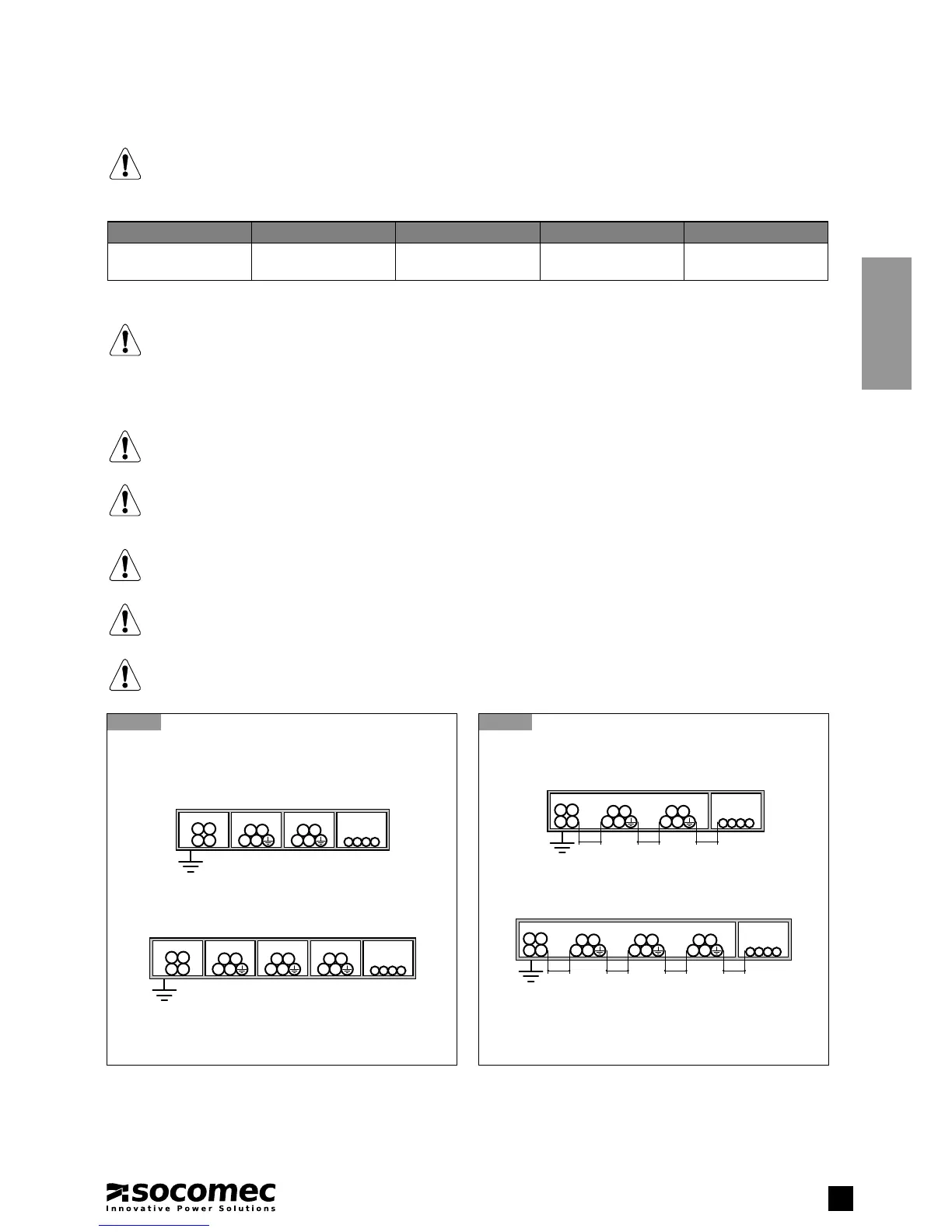
3.2-2
Acceptable installation
3.2-1
Correct installation
3.2. CABLE POSITIONING
NOTE!
This raccomandation must be considered for cables outside the system.
WARNING!
The cables must be installed on trays according to the following diagrams. The trays must be positioned near
the UPS.
WARNING!
All metal and suspended ducts or those in raised flooring MUST be connected to earth and to the various cabinets
WARNING!
Power cables and control cables MUST NEVER be installed in the same duct.
WARNING!
Risk of electromagnetic interference between battery cables and output cables.
Common
Mains Load
N N
Battery
Control
cables
(1)
Mains
Aux
Mains
N N
Battery Load
N
Control
cables
(1)
1. Control cables: connections between the cabinets and each unit, alert signals, remote mimic panel, connection to the BMS
(Building Management System), emergency stop, connection to generator.
Common
Mains Load
N N
Battery
≥10 cm ≥10 cm
Control
cables
(1)
≥10 cm
Mains
Aux
Mains
N N
Battery Load
N
≥10 cm ≥10 cm ≥10 cm ≥10 cm
Control
cables
(1)