24
Installation and Wiring
Step 3: Hang the EV-Charger on the wall for trial, then estimate the required length of AC
input cable and communication cable(s). After that, take the EV-Charger down.
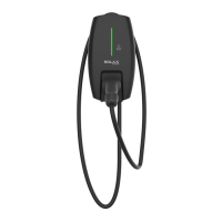
Step 4: Unscrew the EV-Charger's rear cover with the cross screwdriver and take it down.
Then undo the fastening heads and take the waterproof materials away as shown
below.
M4
PlugFastening head Stopper
Figure 6-11 Take down and dissassemble the rear cover
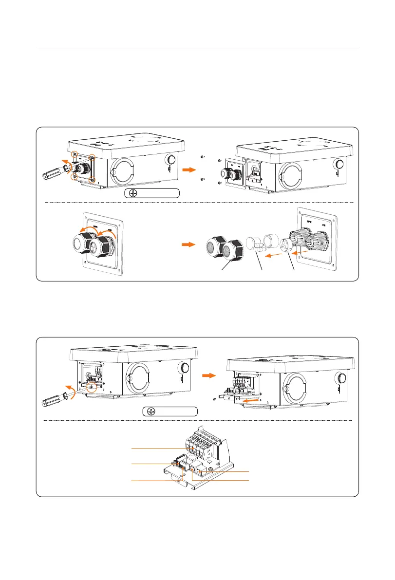
Step 5: Unscrew the countersunk screw of the base plate of communication board with
the cross screwdriver. Then pull the base plate of communication board out. The
connection ports inside are shown as below.
M4
AC input connection port
RJ45 for CT/inveter connection
Network port
Upgrade USB port
RS485 port
Figure 6-12 Pull the base plate of communication board out

 Loading...