28
Installation and Wiring
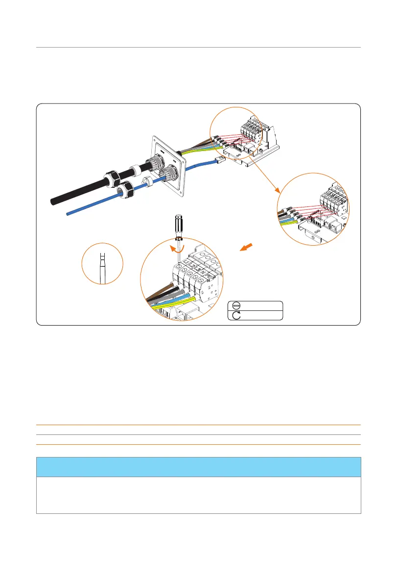
Step 10: Insert the crimped parts of the L1, L2, L3, N and PE wire into the corresponding
holes of the AC input connection port on the base plate of communication
board, then secure the wires with the flat-head screwdriver.
<4 mm
Flat-head
1.5±0.1 N·m
* Insert the crimped part of
L1, L2, L3, N and PE wire
into corresponding holes
Figure 6-21 Connect the AC input cable
Step 11: Connect the communication cable to the corresponding communication port.
Pin definition of communication ports
• Pin definition of RJ45 for connecting CT and inverter
Table 6-1 Pin definition of RJ45 for connecting CT and inverter
Pin 1 2 3 4 5 6 7 8
Pin Definition L1_CT+ L1_CT- L2_CT+ A1 B1 L2_CT- L3_CT+ L3_CT-
* PIN 3, 6, 7, 8 is null for single-phase. Pin 4 & 5 are for connecting inverter.
NOTICE!
• When connecting with inverter, make sure not to use all-pass eight-core
communication cable, please use with the white inverter connector or use two-core
cable instead.

 Loading...