30
Installation and Wiring
NOTICE!
• The arrow on the CT must point at the public grid.
• Do not place the CT on the N Wire or the PE wire.
• Do not place the CT on the N and L wire simultaneously.
• Do not place the CT on the non-insulated wires.
• When using the three-phase CT, please clip the CT clamps on the corresponding
phases (CT-R must be connected to grid L1, CT-S connected to grid L2, CT-T
connected to grid L3).
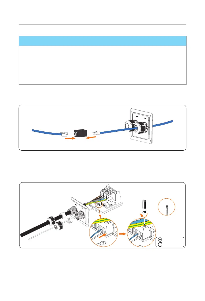
* If extended communication cable is needed when connecting with CT, use the
RJ45 connector to connect the communication cable connected with the EV-
Charger and the other one connected with CT.
EV-ChargerCT
RJ45 connector
(black)
Figure 6-25 Using RJ45 connector
• Communication with Meter
Insert the stripped parts of the conductors into the RS485 port following the Pin
definition and then secure them with flat-head screwdriver.
<2.5 mm
Flat-head
0.4 N·m
Figure 6-26 Connect the communication cable to RS485 port

 Loading...