12 • Recommended Wiring Scheme
________________________________________________________________________________________
For thermistor input programming refer to section 7.6.8 on page 40.
Ground Terminal (terminal Gnd)
Connect thermistor and / or Analogue output shield to this ground terminal.
Analogue Output ( terminals Out (+), Out (-))
Dip switches allow selection between: 0-10VDC, 0-20mA, 4-20mA
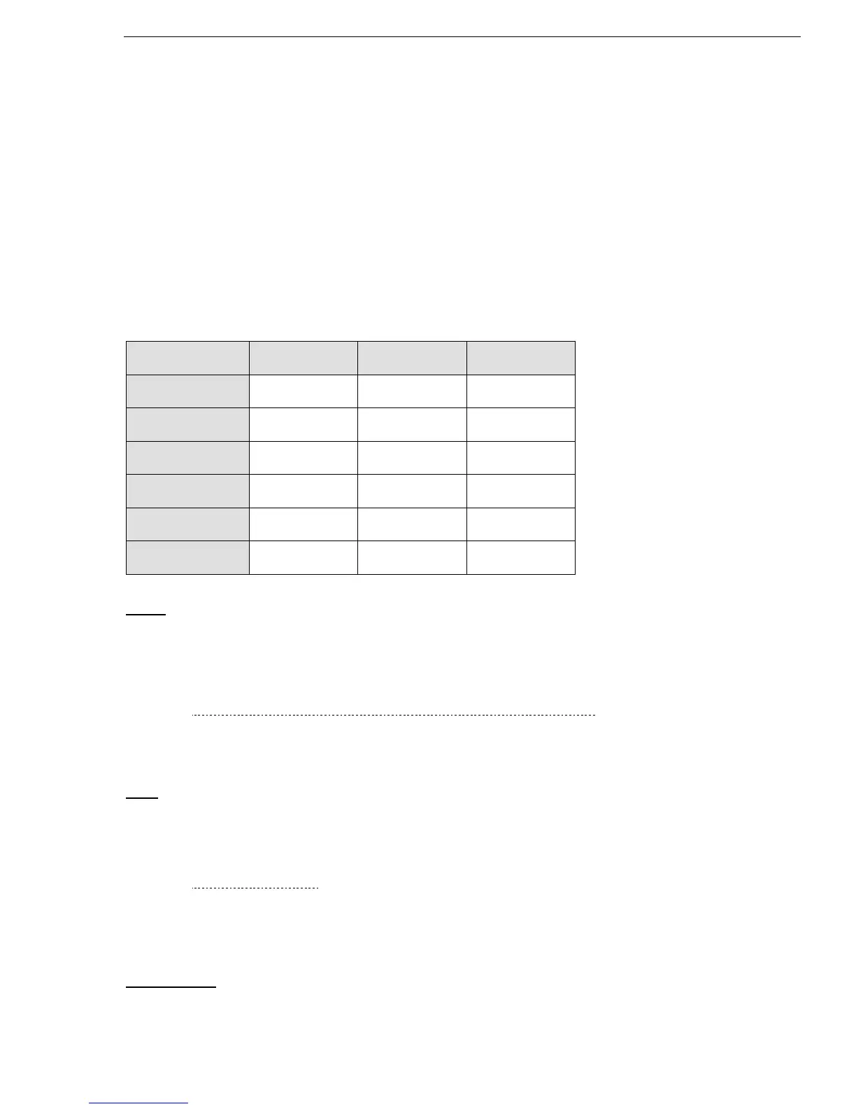
Analogue value can be programmed via the key pad in I/O PROGRAMMING PARAMETERS page to
one of the values as follows: (refer to section
7.6.9 on page 42.)
A. 0….200% of FLA (Default setting)
B. 0….200% of Pn
C. Power factor (POWER FACTOR & POWER measurement only available in RVS-DX58A and up)
* Default
Notes:
• It is important that the RVS-DX is properly grounded, and control module is tightly fastened to the
power section.
• Use twisted shielded cable for thermistor connection.
4.3.8.2 RS-485 Communication (option # 3M) (terminals out(-),Out(+))
Standard RS485, Half Duplex with MODBUS Protocol, baud rate 1200, 2400, 4800, 9600 BPS.
Twisted shielded pair should be used, connect shield to ground a PLC/Computer side.Terminals (-) & (+)
must be wired to control supply for operation in communication mode. Leave terminal NC not connected.
Note: When DeviceNet option is required an external device will be provided with the option.
This gateway is connected via 2 wires to the optional Modbus terminals.
Refer to section 7.6.10 on page 44.
4.3.9 “Inside-Delta” mode
4.3.9.1 General information
When the RVS-DX is installed “Inside Delta”, the individual phases of the Starter are connected in series
with the individual motor windings (6 conductor connections as with the star-delta starter). The soft
starter must only conduct about 67 % (=1\1.5) of the rated motor current. This ensures the use of a
significantly smaller device.
For example:
For a motor with a rated current of 155A motor, a 170A starter will be selected to operate “In-Line”.
For “Inside Delta” starter, we calculate (155 x 67% = 104A) and select a 105A starter.
Less heat dissipates in the cabinet vs. the standard “In-Line” connection.

 Loading...

