8 • Recommended Wiring Scheme
________________________________________________________________________________________
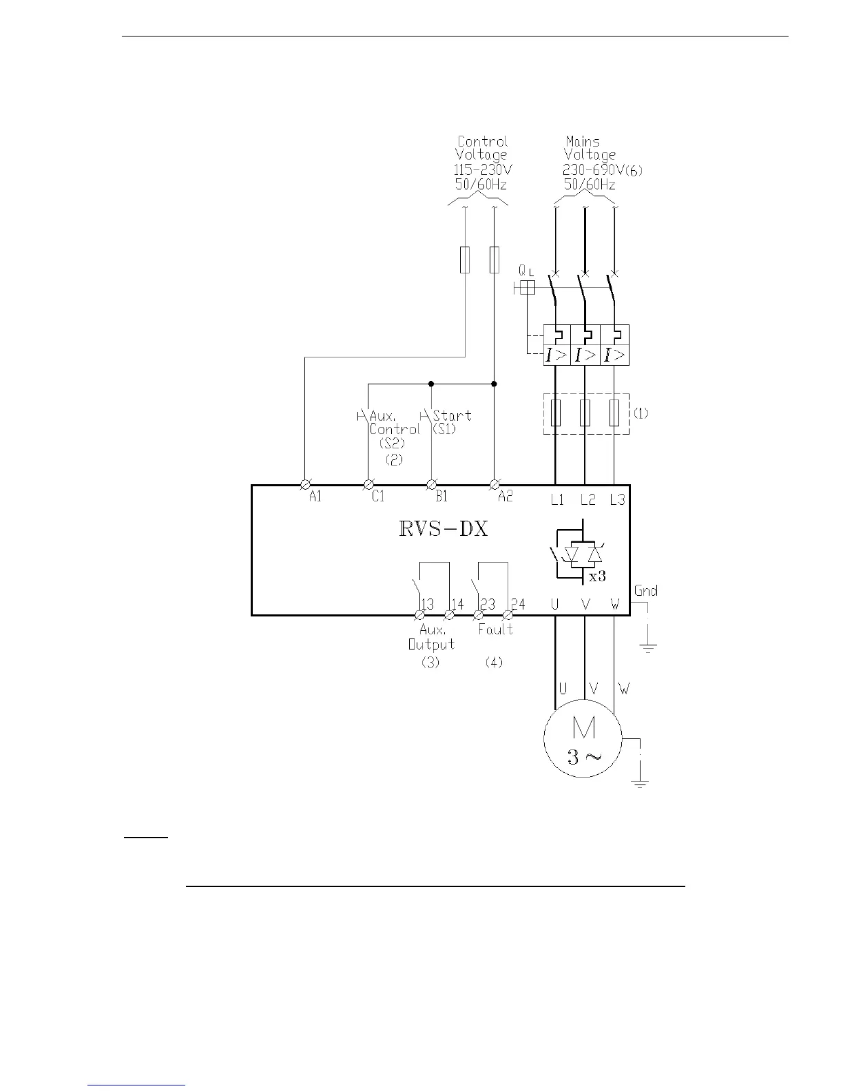
4. RECOMMENDED WIRING SCHEME
4.1 Typical wiring diagram
(1) - Use fuses for type 2 coordination. Refer to section 4.3.1 on page 10
(2) - For Aux. input programming refer to section 7.6.9 on page 42
The use of solid state relays to control the digital inputs B1 and C1 is prohibited
(3) - For Aux. output programming refer to section 7.6.9 on page 42
(4) - Fault relay can function as a “Fault” relay or as a “Fail-Safe” relay. For Fault relay
programming refer to section 7.6.9 on page 42
(5) - When emergency Stop switch is required it is recommended to trip a series contactor
or the feeding circuit breaker. (Not shown)
(6) – Mains voltage of 230-600V available to all models. (need to be specified)
Mains voltage of 690V only available for RVS-DX390A and up.

 Loading...

