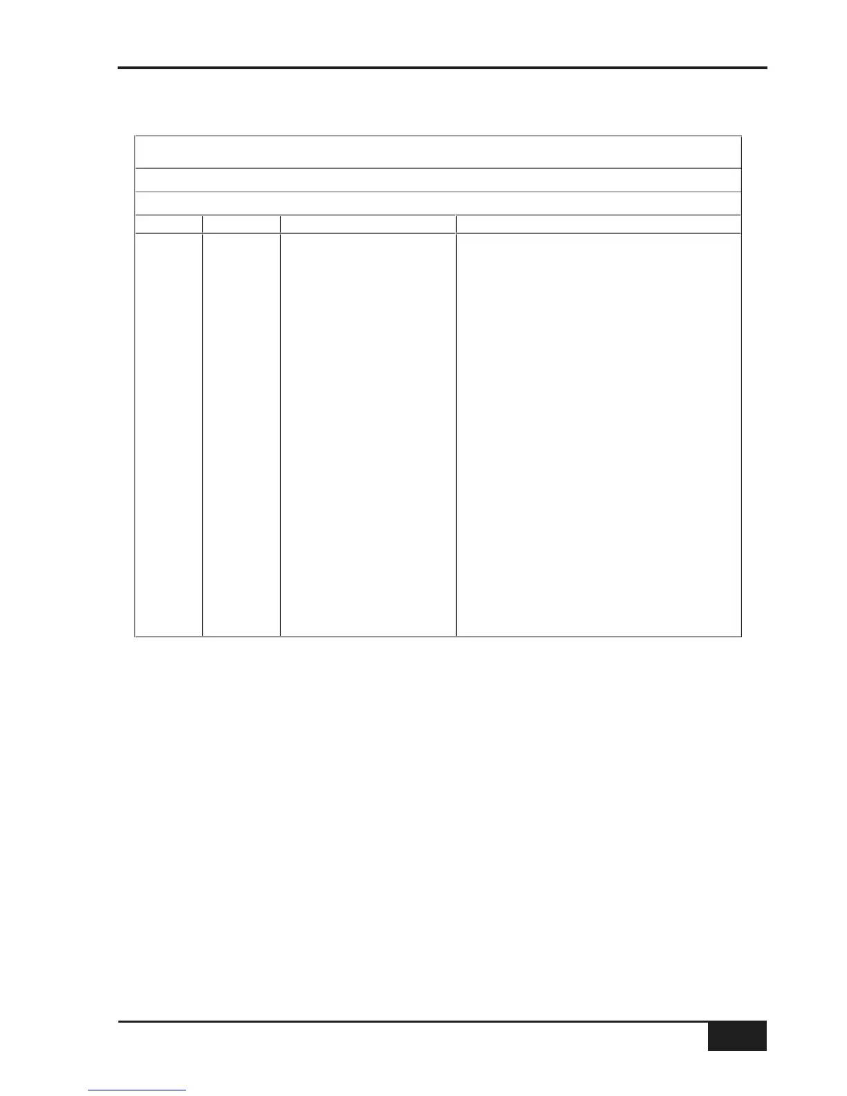
Red Light / Talkback / GPI/O
Location: Rear panel
Connector Type: 25-way D-type female
Pin Ribbon Pin Description Notes
1 5 Red Light Relay contact 'A' Normally open – follows Red Light switch
14 6 Red Light Relay contact 'B' " " "
270V
15 8 GP Input 1 (not used)
3 9 GP Input 2 (not used)
16 10 Monitor Cut Forces Cut when active
4 11 Monitor Dim Forces Dim when active
17 12 Slate Switch
5 13 Listen Switch
18 14 Red Light Switch
6 15 TB All Switch
19 16 FB A Switch
7 17 FB B Switch
20 18 Ext TB Switch
819+4V Max current 200mA (fused)
21 20 Slate Tally
9 21 Listen Tally
22 22 Red Light Tally
10 23 TB All Tally
23 24 FB A Tally
11 25 FB B Tally
24 26 Ext TB Tally
12 27 n/c
25 28 n/c
13 29 n/c
Notes:
All inputs are active low (ie. connect to 0V to activate). Inputs are pulled up to +4V via a 3K9 resistor.
Inputs are diode clamped to 0V and +4V to protect the console circuitry.
All tallies are open collector with a 47R series resistor.
Red Light contacts rated at 125V AC @ 0.5A; 30V DC @ 1A; 110V DC maximum.