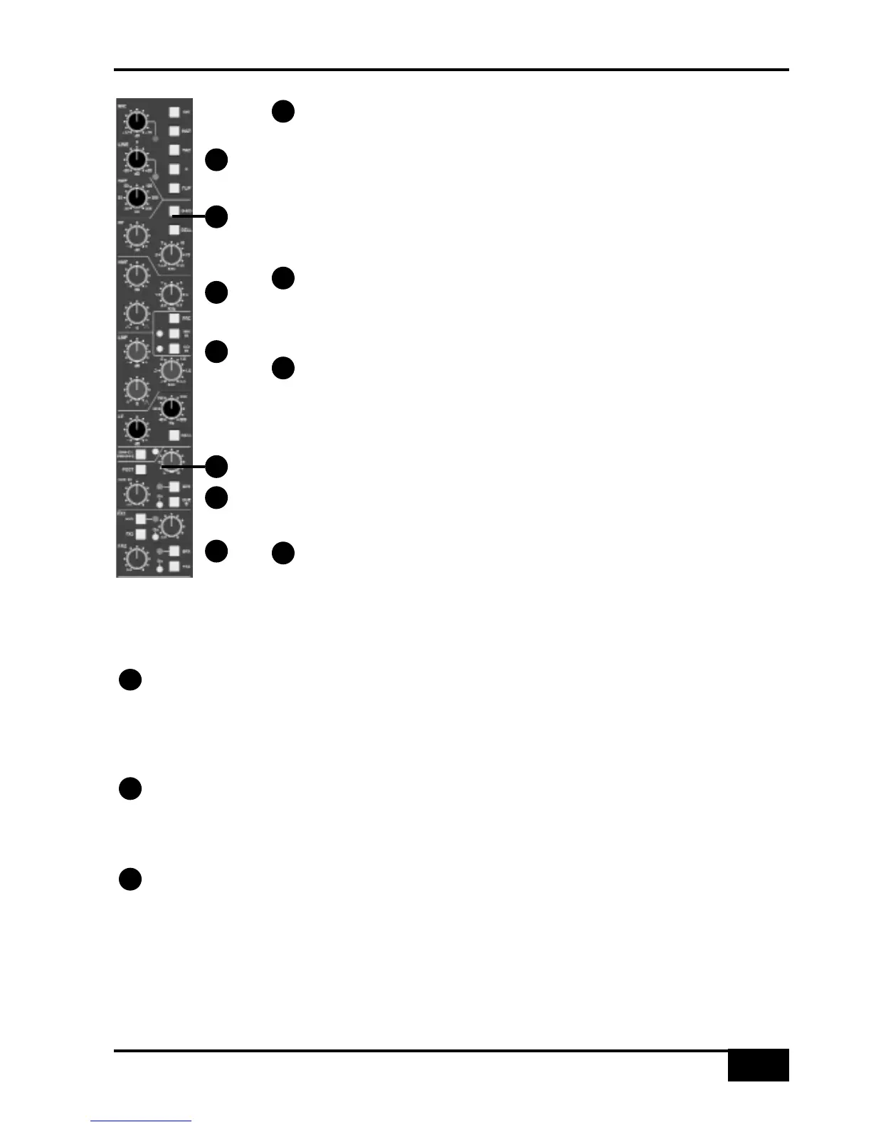
Channel Input Section
This provides a balanced Line Input (XLR connector) with ±20dB of gain (the pot
is indented at unity gain), and a Super Analogue mic amp (XLR connector) with
switchable 48V Phantom Power, 20db PAD. The INST button selects a 1 MΩ high
impedance input (6.35mm jack), suitable for sources such as guitars, for control via the
MIC pot. FLIP toggles the Mic/Instrument (red LED) and Line inputs (green LED).
Note that selecting INST will automatically force selection of the Mic/Instrument. Phase
reverse (Ø) for the selected (balanced) input.
Filter
18dB/Octave high pass filter (HPF). The filter is out of circuit when the control is
fully anticlockwise. When the filter is in circuit, the normally red EQ IN LED lights
green.
Equaliser
The G-EQ button toggles all bands between the default ‘E-Series’ parameters to
the curves and control interaction of ‘G-Series’ EQ. The bands basically function as
follows: HF high frequency shelving equaliser switchable to fixed Q parametric (BELL);
HMF high frequency parametric mid band equaliser; LMF low frequency parametric
mid band equaliser; LF low frequency shelving equaliser switchable to fixed Q
parametric (BELL). The EQ IN button (located next to the insert buttons) routes the
channel signal through the EQ and filter section. When in circuit, the EQ IN LED lights
red. If the filter is also in circuit, this LED changes to green.
Insert Point
The INS IN button routes the channel signal via the balanced insert ‘SEND’ and
‘RTN’ jacks on the rear of the channel module. The insert point defaults to post the
equaliser; PRE places the insert before the equaliser. In conjunction with the Dynamics IP and OP routing
buttons, the order of the EQ, Insert and Dynamics sections can be configured for a wide variety of processing
and routing architectures (see page 4-11 for more on signal processor routing).
Direct Output
DIRECT PRE/EFX button sources the channel direct output from a pre fader signal instead of the default
post fader signal unless an EFX send (see below) is active. If an EFX send is active and PRE/EFX is selected
this is routed to the direct output instead of to the track busses. The PRE/EFX LED lights red to show the direct
output is fed by the pre fader signal or green if fed by an EFX send.
Cue Stereo Send
The Cue Stereo send is normally fed a pre fader signal but can be selected to POST fader. An alternative Cue
Stereo bus may be selected by pressing CUE B. The level pot is fitted with a push-push On/Off switch. Master
controls for the two Cue Stereo outputs are provided in the centre section. See below for details on the EFX button.
FX Sends
Four mono FX send busses are provided. The FX3 and FX4 buttons enable sends 1 and 2 to access
busses 3 and 4. Each level pot is fitted with a push-push On/Off switch. Master controls for these sends are
provided in the centre section.
The EFX buttons isolate the selected send (including Cue Stereo) from its mix bus and route the signals to either
the Track busses, or to the Direct Output if DIRECT PRE/EFX is selected, allowing additional independent effects
send or headphone mixes to be easily generated. Pressing EFX on the stereo send routes Cue Stereo left to
odd Track busses and Cue Stereo right to even busses. Mono FX sends are routed to all Track busses. Note that
only one of the channel aux send controls may feed the EFX system.
Channel Strip
AWS 900+ Owner’s Manual
4-9
1
3
4
5
6
7
2
1
2
3
4
6
5
7