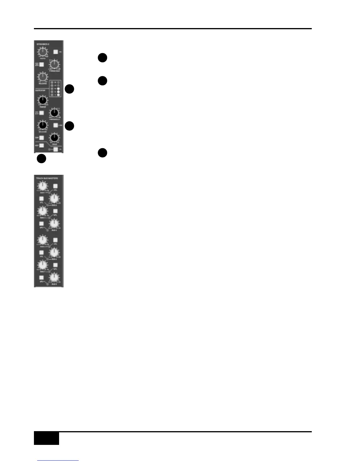
Metering
The yellow and red LEDs indicate the amount of gain reduction the compressor
section is applying.The green LEDs indicate the amount of gain reduction applied
by the Gate/Expander section.
The LINK button links the sidechain signal of that unit to the sidechain of the
other dynamics section. When the two sections are linked, the control voltages of
each section sum together, so that whichever section has the most gain reduction will
control the other section. Don’t try to link two gates using the LINK button when you
want the signal on one to open the other - as soon as one gate closes both will close,
which probably is not what you wanted. If you need to achieve this effect, take a keying
signal from one channel to trigger the other. The easiest way to do this is by patching
from the insert send of the ‘source’ channel into the key input of the appropriate
dynamics section (see below).
The KEY button enables a dynamics section to be controlled by an external
source signal. Connect the source via the appropriate key input jack on the centre
section connector panel.
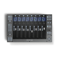
Track Bus Master Controls
The master output level controls for the eight track busses busses (in the top right of
the centre section – see left) all have 10dB of gain when turned fully clockwise. The
controls are indented at the ‘12 o’clock’ position, which corresponds to 0dB gain.
Following level control, the bus outputs can be injected with tone (oscillator TRACK
switch) and talkback (talkback SLATE switch) before being fed to a 25-way D-type on
the centre section connector panel.
An AFL function (post tone and talkback inject) is provided for each bus.The AFL signal
is intelligently assigned to left and right AFL busses. Selecting AFL on a single Track
output will route signal to both left and right AFL busses. Selecting AFL on odd and
even numbered Track outputs will route the odd numbered output to the left AFL bus
and the even numbered output to the right AFL bus.
A set of LCD bargraph meters in the centre section are dedicated to metering the bus
outputs.
Console Operator’s Guide
4-18
AWS 900+ Owner’s Manual
5
6
4
4
5
6