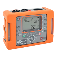
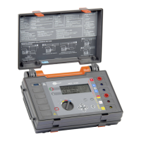
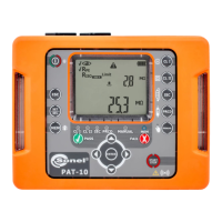
OPERATING MANUAL PAT-1, PAT-2, PAT-2E, PAT-10 version 1.02
+ audible signal + LED diodes flashing
red
Mains voltage > 265 V, measurements are blocked.
+ audible signal + LED diodes flashing
red
Voltage on the test sockets >25 V, measurements are
blocked. Disconnect the tested device with caution.
The allowable inside temperature of the tester has been ex-
ceeded. Wait until the temperature drops (symbol disap-
pears) and start measurements again.
Connect mains power supply to run the test.
Mains power supply connected, power supply polarity is cor-
rect.
Incorrect polarity of power supply, swapped L and N in the
power supply socket of the tester. PAT automatically swaps
L and N in the tester’s test socket, and measurements are
possible.
In order to properly perform the measurement, connect the
measurement probe to the tested device.
In selected measurement function (or autotest with subse-
quent tests in it) after commencing measurement a danger-
ous voltage, from following source, is present: mains - the
device under test will turn on, or a voltage generated during
insulation resistance test (eg. 500V).
An error has been detected. Contact authorized service
point. 'X' refers to an error code.
Turn on the tested Portable Residual Current Device.
The tester can also display a number of other notifications, which are assigned to the different func-
tions of the tester and have been described further in this manual.


 To Next Page