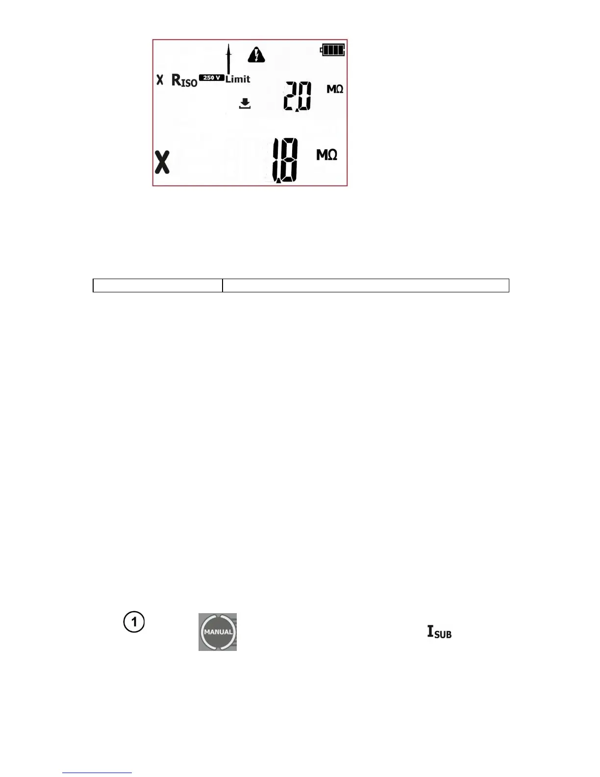
The result is displayed on screen until ESC button is pressed, another test is run
by pressing START/STOP button, measurement mode is changed, settings mode
is activated or the test result is stored in the memory.
More messages displayed by the tester are described in section 2.1.2 of this manual.
Notes:
- Tested device must be turned on.
- Test circuit is electrically isolated from the mains and from mains' PE lead.
- Test result should be read only after displayed values are stabilized.
- After the measurement the tested object is automatically discharged.
4.2.4 Measurement of substitute leakage current - I
SUB
This test is performed to evaluate the condition of insulation of the tested device by determining the
value of leakage current. Leakage current flows from live parts, through insulation, to earth. The leak-
age current includes: current flow through the insulation and capacitances in the device (among oth-
ers from filtering or control systems).Leakage current affects operating safety and, sometimes, caus-
es interference within the power grid.
Particular attention is required for testing devices that are operated in severe conditions, heavy dusti-
ness or high humidity.
During the measurement of substitute leakage current the tester applies test voltage between shorted
L and N of the device tested and PE, in case of class I devices, or probe in case of class II devices.
The measurement is done at the voltage between 25V and 50V, and the value of the measured cur-
rent is scaled proportionally to the value that would occur at the nominal mains voltage supplying the
device. The measuring circuit is galvanically separated from the grid and the from the PE wire.
For Class I appliances, the previous R
PE
test has to have positive result.