OPERATING MANUAL PAT-1, PAT-2, PAT-2E, PAT-10 version 1.02
Correct result. The value
of insulation resistance is
above the set limit. Green
LEDs of PASS indication
are on.
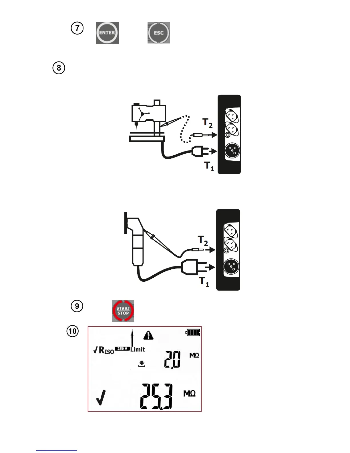
For Class I appliances, the previous R
PE
test has to have positive result. The
measurement is made between shorted L, N and PE. Connection diagram for
Class I appliances (there is possibility, in most cases not required, to carry out the
measurement with the test lead with probe connected to T
2
terminal socket):
Connection diagram for Class II (III) appliances. The test lead with the probe
must be connected to T
2
terminal socket. The measurement is made between
shorted L and N, and the probe: