OPERATING MANUAL PAT-1, PAT-2, PAT-2E, PAT-10 version 1.02
The inspection of the tested device must be carried out.
Among others, examine the following: PE cable and power cables of
the tested device, mains plug (against cracks and burnouts), cable fit-
tings and terminations, housing, air vents, identification plates, covers,
commutators and brushes, windings, bearings, mechanical systems
and other elements that affect proper operation of the device and
safety of the user.
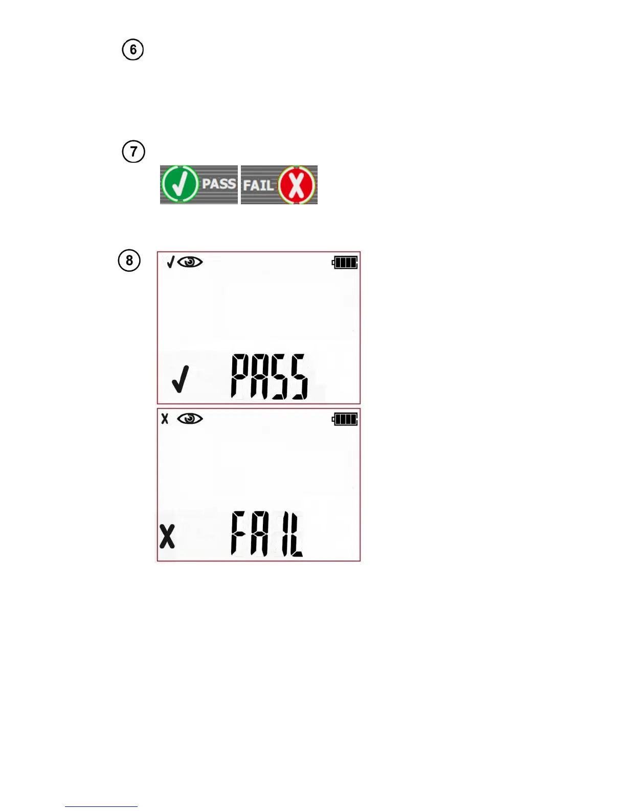
Press PASS (V) or FAIL button
(X) to evaluate the tested de-
vice’s condition: (V) PASS
means positive visual examina-
tion result, (X) FAIL – negative
visual examination result, irregu-
larities were found in the device.
Positive visual inspection
result. Green LEDs of
PASS indication are on.
Negative visual inspection
result. Red LEDs of FAIL
indication are on.
The result is displayed on screen until ESC button is pressed, another test is run
by pressing START button, measurement mode is changed, settings mode is ac-
tivated, tester is switched off or the test result is stored in the memory.
More messages displayed by the tester are described in section 2.1.2 of this manual.
4.2.2 Measurement of PE protective conductor resistance - R
PE
The PE conductor is tested in the 1st protection class devices. The measurement is taken between
the protective contact of the plug (or connection point in case of devices connected permanently) and
metallic parts of the enclosure connected with the PE wire.
 Loading...


