2-4
BRC-300/300P
BRU-300/300P
PM1.7 x 7
CCD cover
CCD covers
CD-389S board
CD flexible cushions
PM1.7 x 7
Prism assembly
Prism assembly
Unsolder
Unsolder
Unsolder
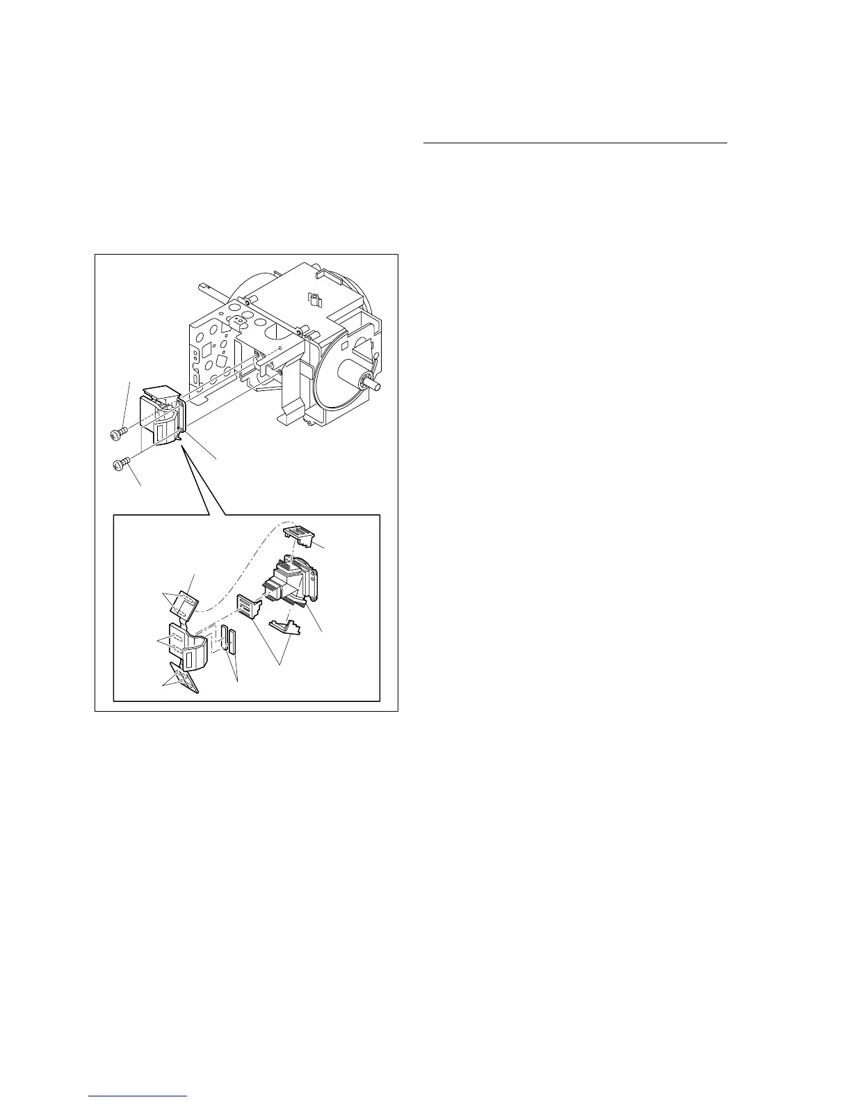
12. Remove the three screws, and remove the prism
assembly.
13. Unsolder the CD-389S board from the prism assembly,
and remove the CD-389S board and three CCD covers.
14. Remove the two CD flexible cushions from the CD-
389S board.
Installation
15. Reassemble the camera assembly in the reverse order
from steps 7 to 14.
m
. Replace the CD flexible cushions with new ones.
. When reattach the CCD covers to the prism assem-
bly, pay attention not to mistake the orientation of
the CCD covers.
. When reattaching the three heat sinks to the board
chassis, insert each heat sink into each hole (Void
between the prism assembly and CCD cover) in the
figure on the previous page.
16. Perform the BRC-300/300P camera block electrical
alignment. (Refer to Section 3-2.)
17. Reassemble the unit in the reverse order from steps 1
to 6.