3-7
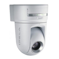
BRC-300/300P
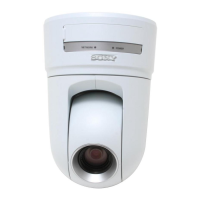
BRU-300/300P
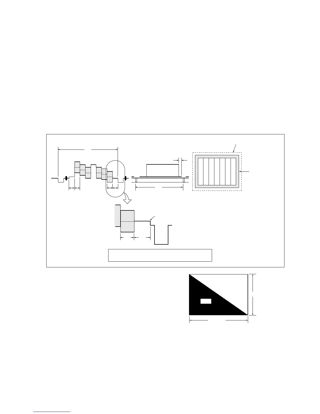
Color bar chart standard picture frame
H
AB
A = B
B
A
0 ±0.1 ms
V
Enlargement
Difference in level
AB
Electronic beam
scanning frame
CRT picture frame
Fig. b. (Color monitor picture)
Yellow
Cyan
Green
White
Magenta
Red
Blue
Yellow
Cyan
Green
White
Magenta
Red
Blue
Fig. a. (Video input/output terminals
output wavefom)
Adjust the camera zoom and direction to obtain the output waveform
shown in Fig. a. and the TV monitor display shown in Fig. b.
3-2-4. Precaution
1. Adjusting Procedure
Perform the adjustments continuously from Sections 3-2-8 to 3-2-21 in order.
2. Subject
(1) Color-bar chart (Standard picture frame)
Adjust the picture frame as shown in the following figure if adjustments are performed using the
color-bar chart.
(2) White pattern (Standard picture frame)
Remove the color-bar chart from the pattern box, and insert a clear chart in its place. (Do not perform
zoom operations during this time.)
841 mm
1189 mm
White
Black
3-2. BRC-300/300P Camera Block Electrical Alignment
(3) Chart for flange back adjustment
Combine a white A0 size (1189 mm x 841 mm) paper
to a black one, and make the chart shown in right
figure.
n
Use the non-reflecting and non-glazing vellum paper
whose size is more than A0, and make the boundary
between white and black to be smoothly flat.