3-3. BRC-300/300P Video Output System Adjustment
3-4. BRU-300/300P Electrical Alignment
3-3-4. SC Frequency Adjustment
n
Before this adjustment, perform “3-3-3. Internal Color-Bar
Adjustment”.
Adjustment Procedure
1. Press the
button of the SIRCS remote commander to
display “EVR_CAM no:001 data:xxx”.
2. Adjust “data” using the
/ button so that the frequen-
cy counter satisfies the specification.
Adjustment item: Data of EVR_CAM no:001
Specification: 3579545 ±5 Hz (NTSC)
4433618 ±5 Hz (PAL)
3. Press the BACK LIGHT button of the SIRCS remote
commander to output a video signal.
4. Check that the video signal is normal, and turn off the
power of all the equipment.
5. When the EX-947 board is not connected, return the
switch S1003-3 on the SY-314 board to OFF, and
reattach the base plate. (Refer to Section 1-3-4.)
6. Remove the EX-947 board, and reattach the blank
panel or the optional board.
(Refer to Section 1-3-5.)
3-4. BRU-300/300P Electrical Alignment
3-4-1. Tools/Equipment
. SC detection tool
n
Use the test signal generator TG-7 (SHIBASOKU) or
equivalent.
. Frequency counter
. Analog composite waveform monitor
. Color monitor
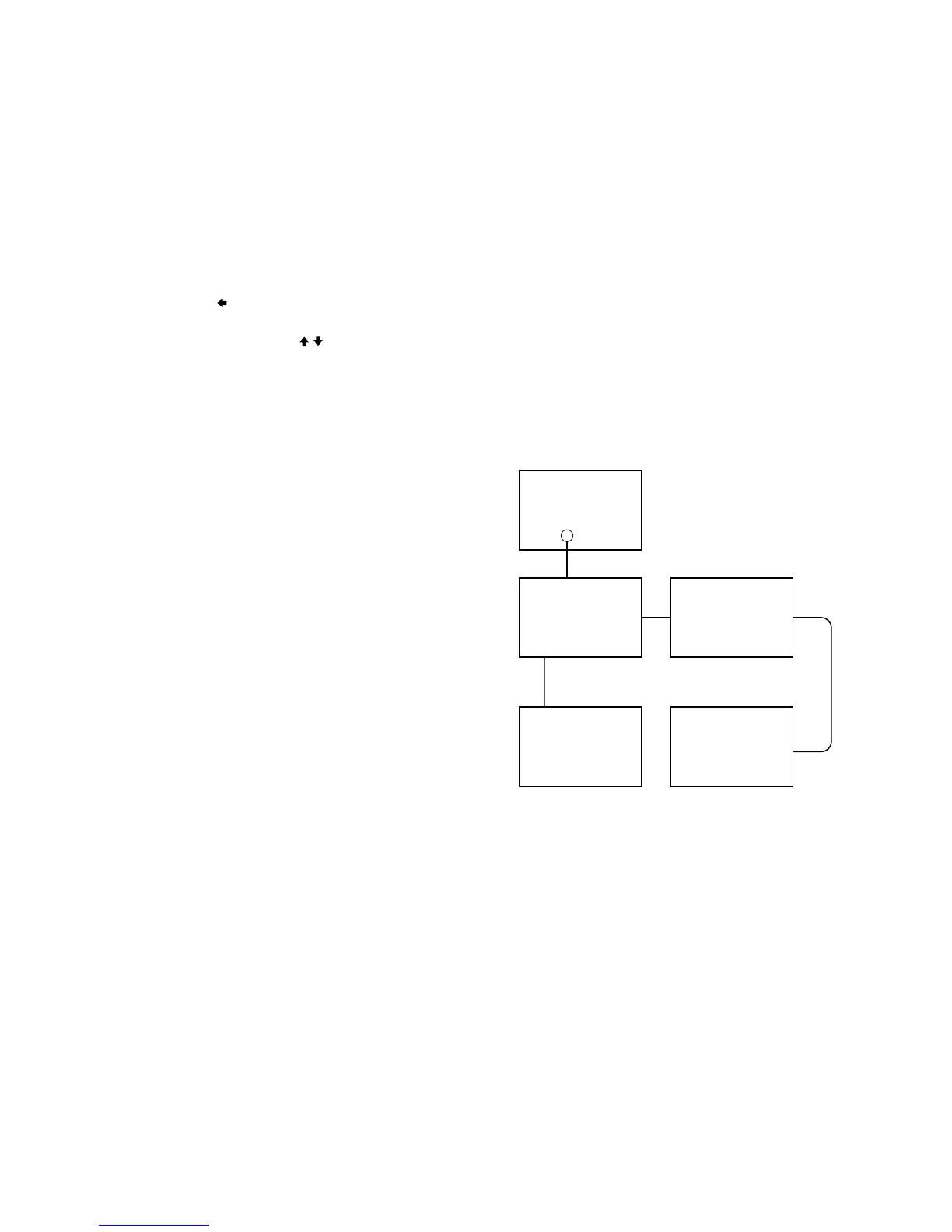
3-4-2. Connection Diagram



 To Next Page