3-20
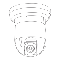
BRC-300/300P
BRU-300/300P
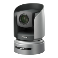
H
A
Center of luminance line
3-2-8. 66 MHz/54 MHz Origin Oscillation
Adjustment
Set the frequency of the clock for synchronization.
If the following specified value is not satisfied, the syn-
chronization will be disrupted and the color will become
inconsistent.
Subject Arbitrary
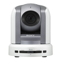
Measurement point VC-343 board, pin 6 of IC503
Measuring instrument Frequency counter (through the
oscilloscope)
Adjustment page F
Adjustment address 10
Specification f = 33000000 ±165 Hz (NTSC)
f = 27000000 ±135 Hz (PAL)
m
. The data of page: 0, address: 10 must be “00”.
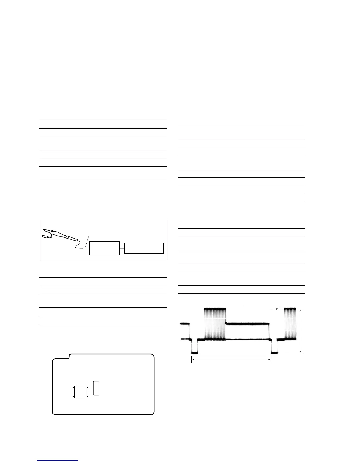
. Connect the equipments as shown in the figure.
. Terminate the probe of the oscilloscope with 75 Z.
Adjusting procedure
Order Page Address Data Procedure
1 0 01 01 Set the data.
2 F 10 Change the data to satisfy the
specification f.
3 F 10 Press PAUSE button.
4 0 01 00 Set the data.
3-2. BRC-300/300P Camera Block Electrical Alignment
Probe
75 Z terminator
Oscilloscope Frequency counter
6449
1732
1
16
48
33
IC503
VC-343 board
3-2-9. Video System Adjustments
m
. Perform this adjustments after performing “3-2-8. 66
MHz/54 MHz Origin Oscillation Adjustment”.
. Check that the data of page: 0, address: 10 is “00”. If
not, set data: 00 to this address.
. Terminate the probe of the oscilloscope with 75 Z.
Y Output Level Adjustment
Mode Camera
Subject Arbitrary
Measurement point DD-208 board, pin 6 of CN151
(75 Z terminated)
Measuring instrument Oscilloscope
Adjustment page C
Adjustment address 25
Specification Y output level: A = 1000 ±14 mV
Adjusting procedure
Order Page Address Data Procedure
1 0 01 01 Set the data.
2 3 0C 02 Set the data, and press
PAUSE button.
3 C 25 Change the data to satisfy the
specification A.
4 C 25 Press PAUSE button.
5 3 0C 00 Set the data, and press
PAUSE button.
6 0 01 00 Set the data.